Infiniti Q45 (FY33). Manual — part 481
RHA888H
Multiplex Communication Circuit
DIAGNOSTIC PROCEDURE
SYMPTOM:
I
A/C system does not come on.
I
A/C system can not controlled.
1
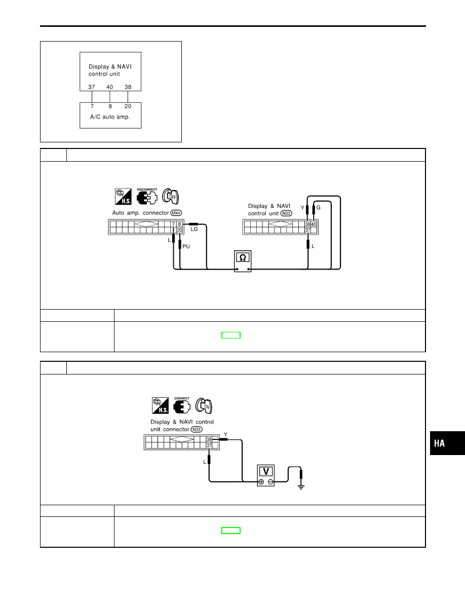
CHECK CIRCUIT CONTINUITY BETWEEN DISPLAY & NAVI CONTROL UNIT AND AUTO AMP.
Check circuit continuity between each terminal on Display & Navigation control unit and on auto amp.
RHA889HA
Continuity should exist.
If OK, check harness for short.
OK or NG
OK
E
GO TO 2.
NG
E
1. Repair harness or connector.
2. Go to “OPERATIONAL CHECK”, HA-33.
Confirm that A/C system is in good order.
2
CHECK MULTI-PLEX COMMUNICATION SIGNAL
Do approx. 3.5 volts exist between Display & NAVI control unit harness terminal Nos. 37, 38 and body ground?
RHA890HA
Yes or No
Yes
E
GO TO 3.
No
E
1. Replace auto amp.
2. Go to “OPERATIONAL CHECK”, HA-33.
Confirm that A/C system is in good order.
GI
MA
EM
LC
EC
FE
AT
PD
FA
RA
BR
ST
RS
BT
EL
IDX
TROUBLE DIAGNOSES
HA-89
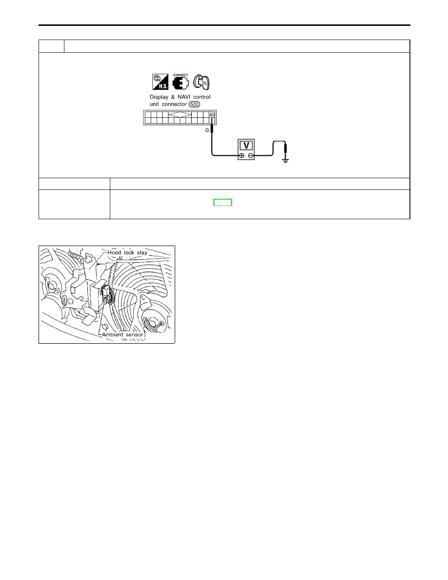
3
CHECK MULTIPLEX COMMUNICATION SIGNAL
Do approx. 3.5 volts exist between auto amp. harness terminal No. 40 and body ground?
RHA891HA
Yes or No
Yes
E
INSPECTION END.
No
E
1. Replace Display & NAVI control unit.
2. Go to “OPERATIONAL CHECK”, HA-33.
Confirm that A/C system is in good order.
RHA967F
Ambient Sensor Circuit
COMPONENT DESCRIPTION
The ambient sensor is attached in front of the driver’s side con-
denser. It detects ambient temperature and converts it into a resis-
tance value which is then input to the auto amplifier.
AMBIENT TEMPERATURE INPUT PROCESS
The automatic amplifier includes a “processing circuit” for the ambi-
ent sensor input. However, when the temperature detected by the
ambient sensor increases quickly, the processing circuit retards the
auto amp. function. It only allows the auto amp. to recognize an
ambient temperature increase of 0.33°C (0.6°F) per 100 seconds.
As an example, consider stopping for a cup of coffee after high
speed driving. Although the actual ambient temperature has not
changed, the temperature detected by the ambient sensor will
increase. This is because the heat from the engine compartment
can radiate to the front grille area, location of the ambient sensor.
TROUBLE DIAGNOSES
Multiplex Communication Circuit (Cont’d)
HA-90
RHA955F
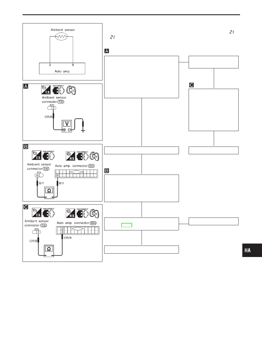
DIAGNOSTIC PROCEDURE
SYMPTOM: Ambient sensor circuit is open or shorted. (
or
−
appears on the display as a result of conducting Self-di-
agnosis STEP 2.)
RHA901F
RHA902F
RHA903F
CHECK AMBIENT SENSOR CIRCUIT
BETWEEN AMBIENT SENSOR AND
AUTO AMP.
Disconnect ambient sensor harness con-
nector.
Do approx. 5 volts exist between ambient
sensor harness terminal No.
q
2
and body
ground?
Yes
E
No
Disconnect auto amp. har-
ness connector.
Note
Check circuit continuity
between ambient sensor
harness
terminal
No.
q
2
and auto amp. harness ter-
minal No.
q
2
.
Continuity should exist.
If OK, check harness for
short.
OK
Disconnect auto amp. harness connector.
Replace auto amp.
Note
Check circuit continuity between ambient
sensor harness terminal No.
q
9
and auto
amp. harness terminal No.
q
9
.
Continuity should exist.
If OK, check harness for short.
OK
CHECK AMBIENT SENSOR.
(Refer to HA-92.)
OK
E
NG
Replace ambient sensor.
Replace auto amp.
Note:
If the result is NG or No after checking circuit continuity, repair harness
or connector.
GI
MA
EM
LC
EC
FE
AT
PD
FA
RA
BR
ST
RS
BT
EL
IDX
TROUBLE DIAGNOSES
Ambient Sensor Circuit (Cont’d)
H
H
H
H
H
H
HA-91
RHA933F
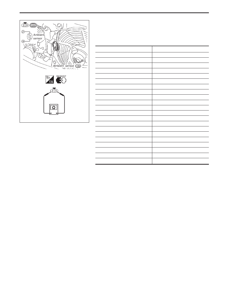
COMPONENT INSPECTION
Ambient sensor
After disconnecting ambient sensor harness connector, measure
resistance between terminals
q
9
and
q
2
at sensor harness side,
using the table below.
Temperature °C (°F)
Resistance k
Ω
−35 (−31)
38.35
−30 (−22)
28.62
−25 (−13)
21.61
−20 (−4)
16.50
−15 (5)
12.73
−10 (14)
9.92
−5 (23)
7.80
0 (32)
6.19
5 (41)
4.95
10 (50)
3.99
15 (59)
3.24
20 (68)
2.65
25 (77)
2.19
30 (86)
1.81
35 (95)
1.51
40 (104)
1.27
45 (113)
1.07
50 (122)
0.91
55 (131)
0.77
60 (140)
0.66
65 (149)
0.57
TROUBLE DIAGNOSES
Ambient Sensor Circuit (Cont’d)
HA-92
Нет комментариевНе стесняйтесь поделиться с нами вашим ценным мнением.
Текст