Infiniti Q45 (FY33). Manual — part 153
SEF176Y
SEF549P
Procedure for malfunction B
CAUTION:
Always drive vehicle at a safe speed.
TESTING CONDITION:
This test may be conducted with the drive wheels lifted in the
shop or by driving the vehicle. If a road test is expected to be
easier, it is unnecessary to lift the vehicle.
1) Wait until engine coolant temperature is less than 90°C
(194°F).
(a) Turn ignition switch “ON”.
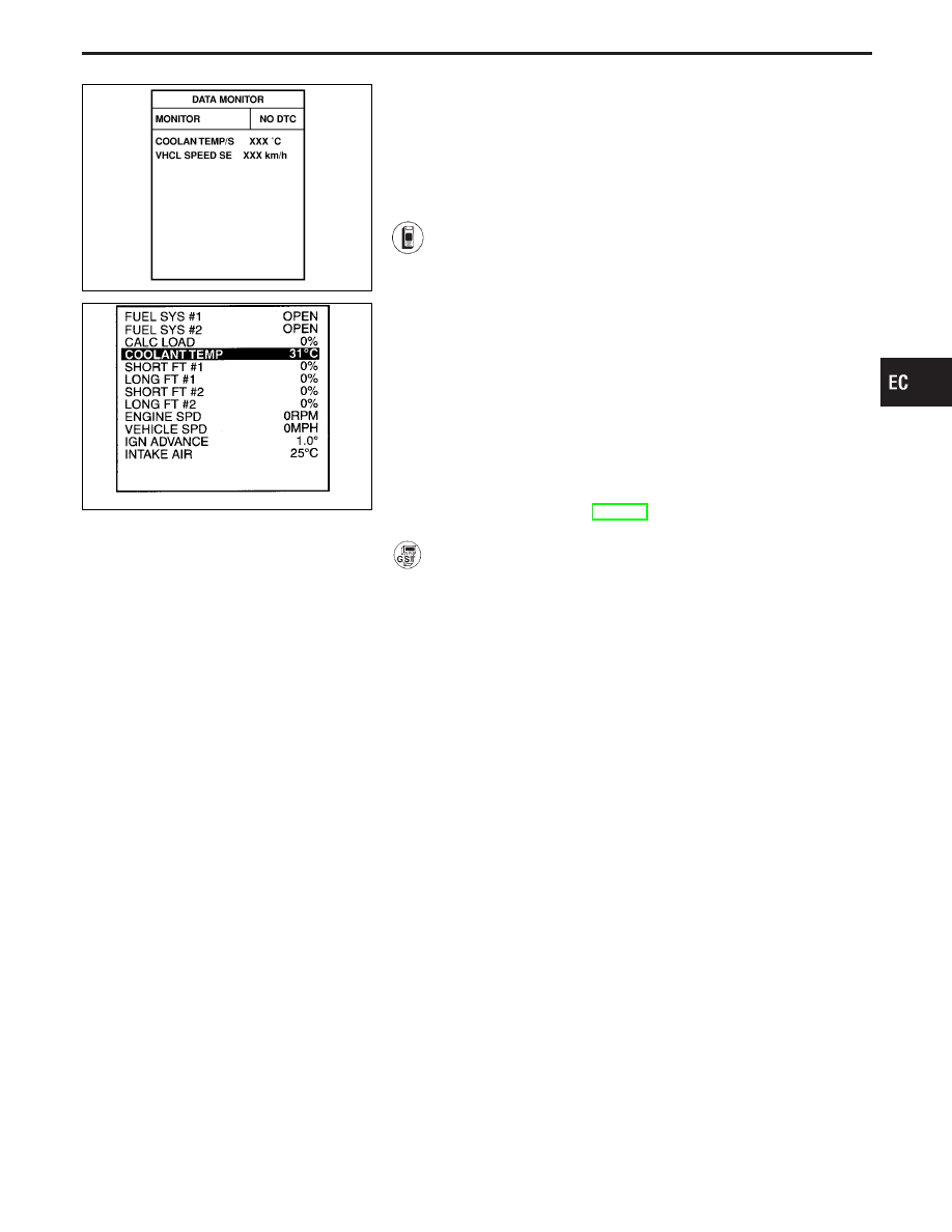
(b) Select “DATA MONITOR” mode with CONSULT-II.
(c) Check the engine coolant temperature.
(d) If the engine coolant temperature is not less than
90°C (194°F), turn ignition switch “OFF” and cool
down engine.
I
Perform the following steps before engine coolant tem-
perature is above 90°C (194°F).
2) Turn ignition switch “ON”.
3) Select “DATA MONITOR” mode with CONSULT-II.
4) Start engine and turn TCS switch “OFF”.
5) Hold vehicle speed more than 70 km/h (43 MPH) for
100 consecutive seconds.
6) If 1st trip DTC is detected, go to “DIAGNOSTIC
PROCEDURE”, EC-143.
------------------------------------------------------------------------------------------------------------------------------------------------------------------------------------------------------------------------------------------------------ OR ------------------------------------------------------------------------------------------------------------------------------------------------------------------------------------------------------------------------------------------------------
Follow the procedure “With CONSULT-II” above.
GI
MA
EM
LC
FE
AT
PD
FA
RA
BR
ST
RS
BT
HA
EL
IDX
TROUBLE DIAGNOSIS FOR DTC P0110
Intake Air Temperature Sensor (Cont’d)
EC-141
TEC042M
TROUBLE DIAGNOSIS FOR DTC P0110
Intake Air Temperature Sensor (Cont’d)
EC-142
SEF051T
SEF321R
SEF322R
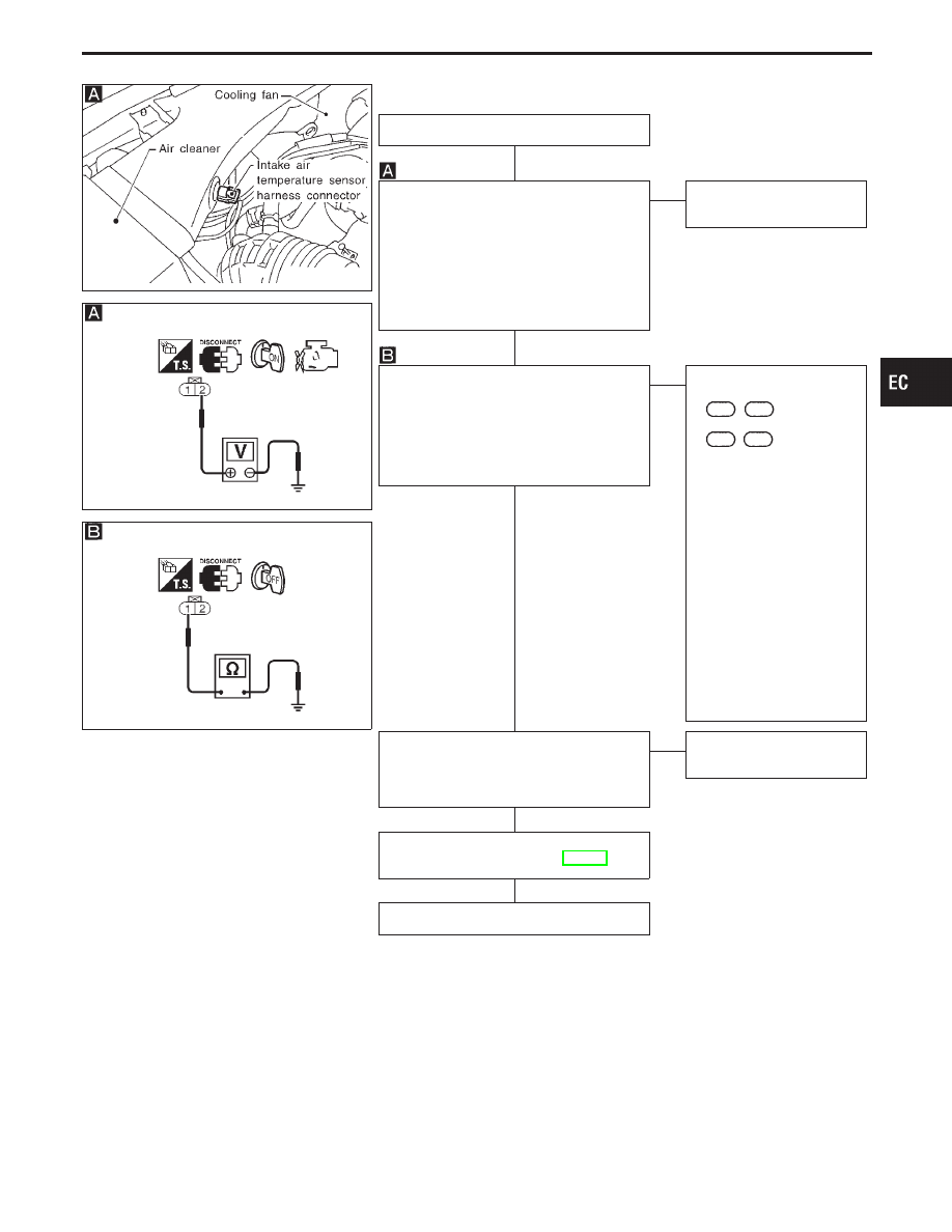
DIAGNOSTIC PROCEDURE
INSPECTION START
CHECK POWER SUPPLY.
1. Turn ignition switch “OFF”.
2. Disconnect intake air temperature sen-
sor harness connector.
3. Turn ignition switch “ON”.
4. Check voltage between terminal
q
2
and ground.
Voltage:
Approximately 5V
OK
E
NG
Repair harness or connec-
tors.
CHECK GROUND CIRCUIT.
1. Turn ignition switch “OFF”.
2. Check harness continuity between ter-
minal
q
1
and engine ground.
Continuity should exist.
If OK, check harness for short to
power.
OK
E
NG
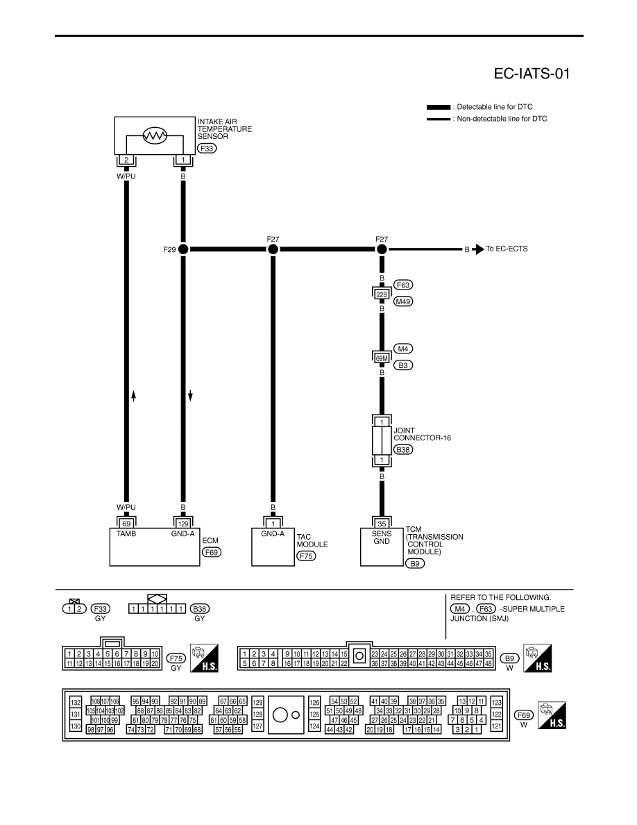
Check the following.
I
Harness connectors
F63
,
M49
I
Harness connectors
M4
,
B3
I
Joint connector-16
I
Harness for open or
short between ECM and
intake air temperature
sensor
I
Harness for open or
short between air tem-
perature sensor and
throttle actuator control
(TAC) module
I
Harness for open or
short between TCM
(Transmission Control
Module) and intake air
temperature sensor
If NG, repair open circuit or
short to power in harness
or connectors.
CHECK COMPONENT
(Intake air temperature sensor).
Refer to “COMPONENT INSPECTION” on
next page.
OK
E
NG
Replace intake air tem-
perature sensor.
Perform “TROUBLE DIAGNOSIS FOR
INTERMITTENT INCIDENT”, EC-117.
INSPECTION END
GI
MA
EM
LC
FE
AT
PD
FA
RA
BR
ST
RS
BT
HA
EL
IDX
TROUBLE DIAGNOSIS FOR DTC P0110
Intake Air Temperature Sensor (Cont’d)
H
H
H
H
H
EC-143
SEF947Q
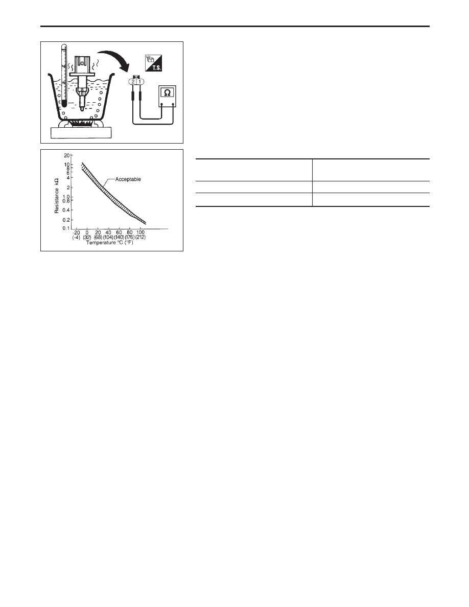
COMPONENT INSPECTION
Intake air temperature sensor
Check resistance as shown in the figure.
SEF012P
<Reference data>
Intake air temperature
°C (°F)
Resistance k
Ω
20 (68)
2.1 - 2.9
80 (176)
0.27 - 0.38
If NG, replace intake air temperature sensor.
TROUBLE DIAGNOSIS FOR DTC P0110
Intake Air Temperature Sensor (Cont’d)
EC-144
Нет комментариевНе стесняйтесь поделиться с нами вашим ценным мнением.
Текст