Infiniti Q45 (FY33). Manual — part 486
Intake Door Motor Circuit
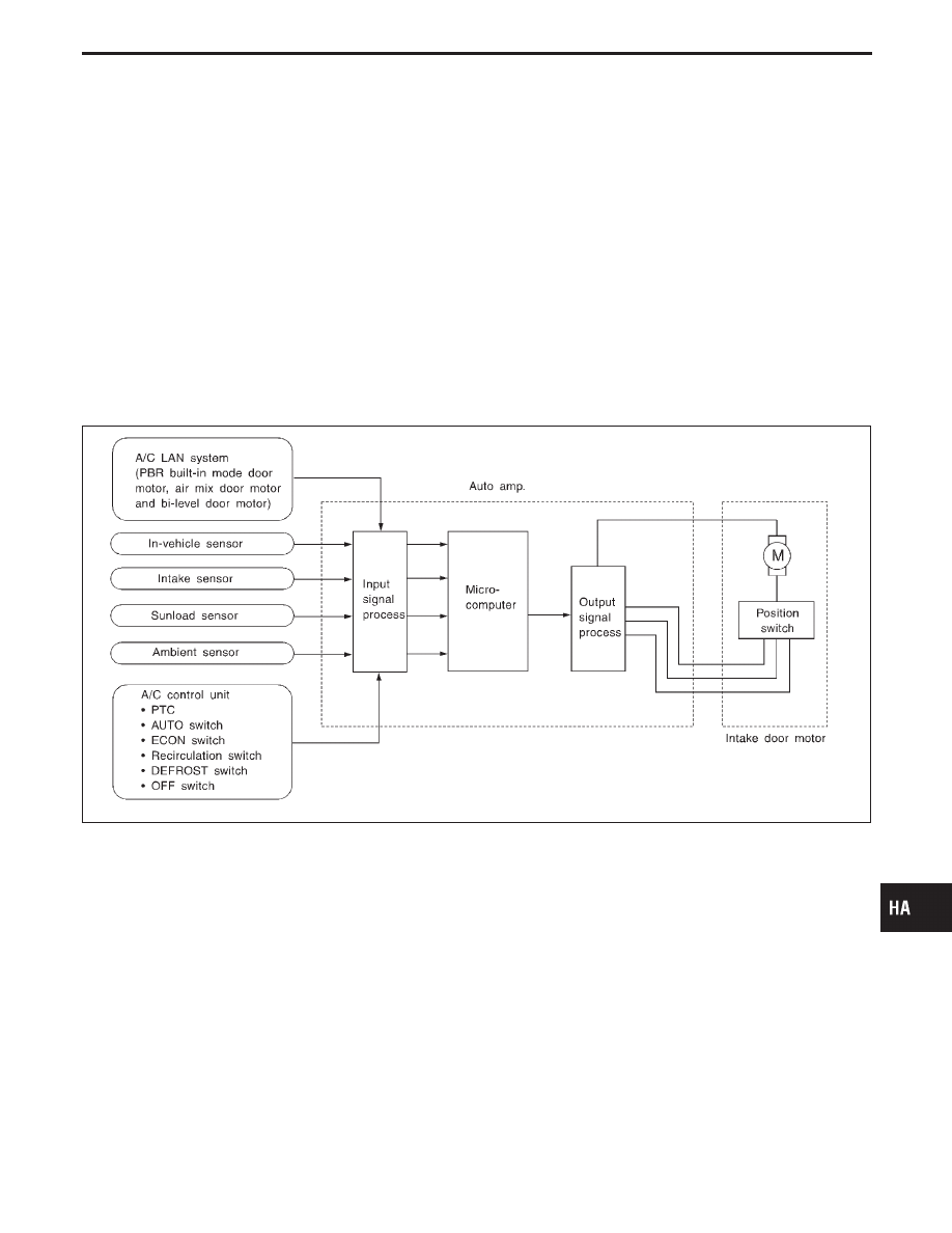
SYSTEM DESCRIPTION
Component parts
Intake door control system components are:
1) Auto amplifier
2) Intake door motor
3) A/C LAN system (PBR)
4) In-vehicle sensor
5) Ambient sensor
6) Sunload sensor
7) Intake sensor
8) A/C control unit (PTC, AUTO, ECON, DEFROST, REC, OFF switches)
System operation
The intake door control determines intake door position based on the ambient temperature and the in-vehicle
temperature. When the ECON, DEFROST, or OFF switches are pushed, the auto amplifier sets the intake door
at the “Fresh” position.
RHA174H
GI
MA
EM
LC
EC
FE
AT
PD
FA
RA
BR
ST
RS
BT
EL
IDX
TROUBLE DIAGNOSES
HA-109
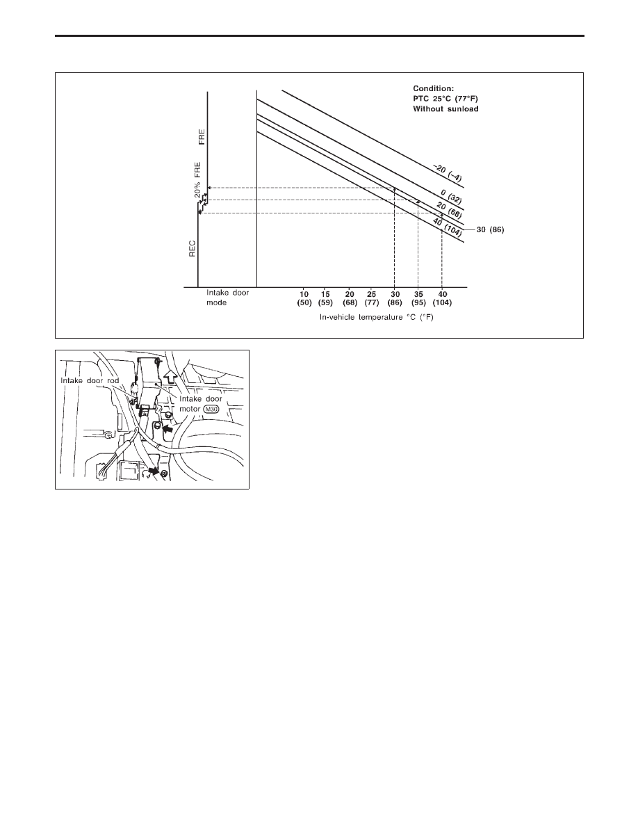
Intake door control specification
RHA977FA
RHA938F
COMPONENT DESCRIPTION
The intake door motor is attached to the intake unit. It rotates so
that air is drawn from inlets set by the auto amplifier. Motor rota-
tion is conveyed to a lever which activates the intake door.
TROUBLE DIAGNOSES
Intake Door Motor Circuit (Cont’d)
HA-110
RHA962F
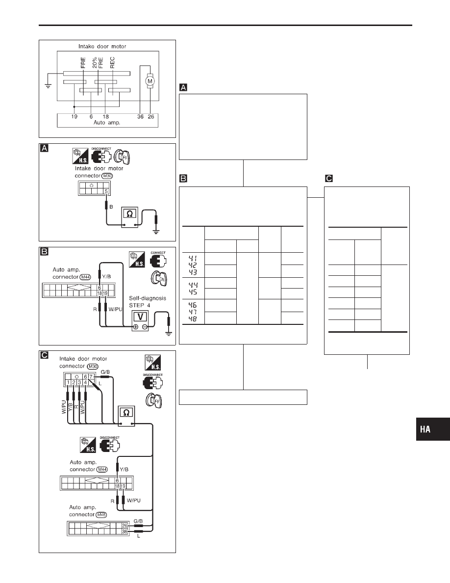
DIAGNOSTIC PROCEDURE
SYMPTOM: Intake door motor does not operate normally.
I
Perform Preliminary Check 2 before referring to the fol-
lowing flow chart.
RHA916F
RHA542FA
RHA917F
Note
CHECK BODY GROUND CIRCUIT FOR
INTAKE DOOR MOTOR.
Disconnect intake door motor harness
connector.
Does continuity exist between intake door
motor harness terminal
q
5
and body
ground?
Yes
Note
CHECK FOR AUTO AMP. OUTPUT.
Set up Self-diagnosis STEP 4.
Measure voltage across auto amp. har-
ness terminals and body ground.
OK
E
NG
Check circuit continuity
between each terminal on
auto amp. and on intake
door motor.
If OK, check harness for
short.
OK
q
A
(Go to next page.)
INSPECTION END
Note:
If the result is NG or No after checking circuit continuity, repair harness
or connector.
Code
No.
Terminal No.
Condi-
tion
Volt-
age
V
!
@
q
6
Body
ground
REC
5
q
18
or
q
19
0
q
19
20%
FRE
5
q
6
or
q
18
0
q
18
FRE
5
q
6
or
q
19
0
0V: Approx. 0V
5V: Approx. 5V
Terminal No.
Continu-
ity
Auto
amp.
Intake
door
motor
q
19
q
4
Yes
q
6
q
2
q
18
q
3
q
19
q
1
q
26
q
7
q
36
q
6
GI
MA
EM
LC
EC
FE
AT
PD
FA
RA
BR
ST
RS
BT
EL
IDX
TROUBLE DIAGNOSES
Intake Door Motor Circuit (Cont’d)
H
H
H
HA-111
RHA912F
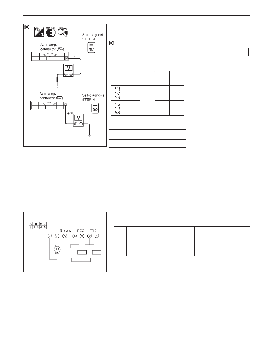
q
A
CHECK FOR AUTO AMP. OUTPUT.
Set up Self-diagnosis STEP 4.
Measure voltage across auto amp. harness
terminals and body ground.
OK
E
NG
Replace auto amp.
Replace intake door motor.
Code
No.
Terminal No.
Condi-
tion
Voltage
V
!
@
q
26
Body
ground
REC
12
q
36
0
q
26
FRE
0
q
36
12
0V: Approx. 0V
12V: Approx. 12V
RHA973F
COMPONENT INSPECTION
Intake door motor
6
7
Intake door operation
Movement of link rotation
!
@
REC
,
FRE
Counterclockwise
—
—
STOP
STOP
@
!
FRE
,
REC
Clockwise
TROUBLE DIAGNOSES
Intake Door Motor Circuit (Cont’d)
H
H
HA-112
Нет комментариевНе стесняйтесь поделиться с нами вашим ценным мнением.
Текст