Infiniti Q45 (FY33). Manual — part 170

AEC158A
COMPONENT INSPECTION
Heated oxygen sensor 1 heater (front)
Check resistance between terminals
q
3
and
q
1
.
Resistance: 2.3 - 4.3
Ω
at 25°C (77°F)
Check continuity between terminals
q
2
and
q
1
,
q
3
and
q
2
.
Continuity should not exist.
If NG, replace the heated oxygen sensor 1 (front).
CAUTION:
I
Discard any heated oxygen sensor which has been dropped
from a height of more than 0.5 m (19.7 in) onto a hard sur-
face such as a concrete floor; use a new one.
I
Before installing new oxygen sensor, clean exhaust system
threads
using
Oxygen
Sensor
Thread
Cleaner
tool
J-43897-18 or J-43897-12 and approved anti-seize lubricant.
GI
MA
EM
LC
FE
AT
PD
FA
RA
BR
ST
RS
BT
HA
EL
IDX
TROUBLE DIAGNOSIS FOR DTC P0135 (B1), P0155 (B2)
Heated Oxygen Sensor 1 Heater (Front) (P0135:
Bank 1), (P0155: Bank 2) (Cont’d)
EC-209
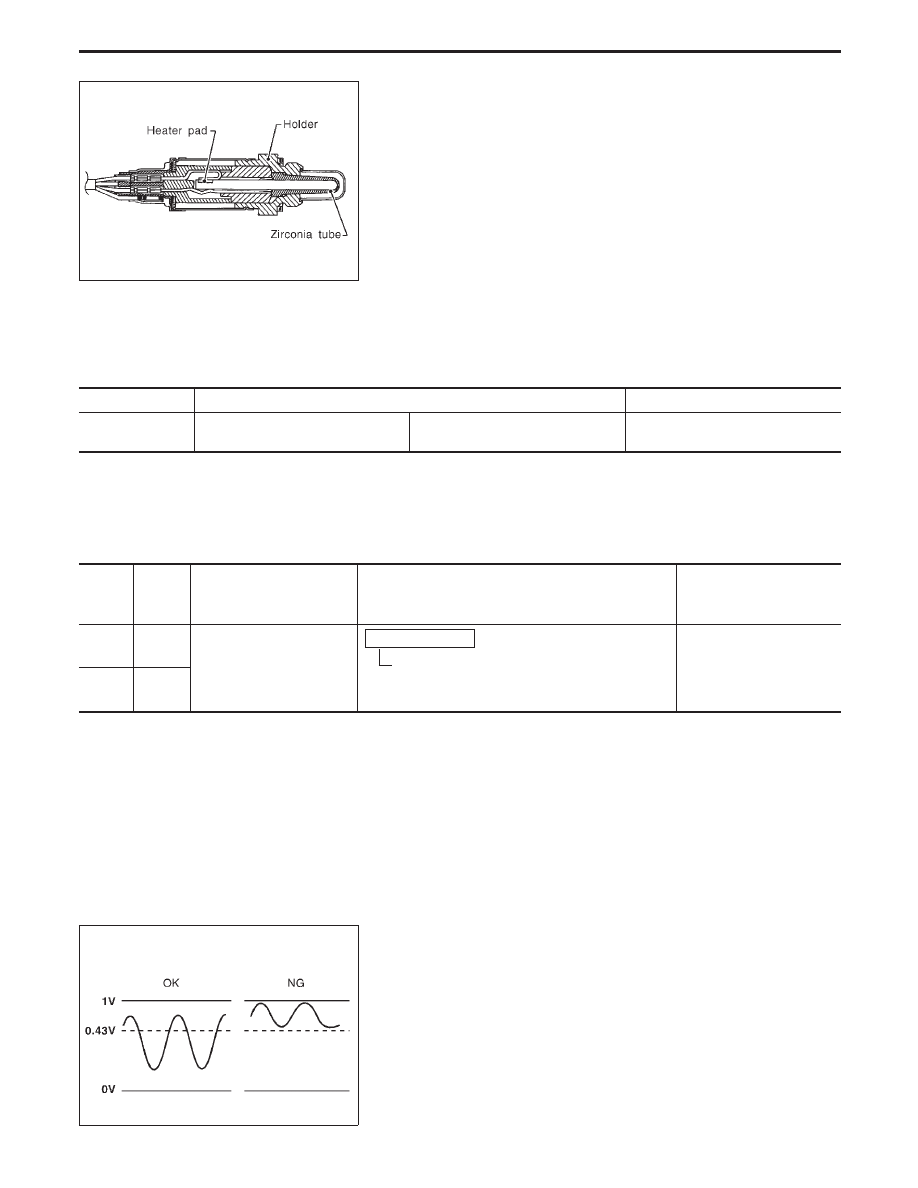
SEF327R
Heated Oxygen Sensor 2 (Rear) (P0137: Bank
1), (P0157: Bank 2) (Min. Voltage Monitoring)
COMPONENT DESCRIPTION
The heated oxygen sensor 2 (rear), after three way catalyst, moni-
tors the oxygen level in the exhaust gas on each bank.
Even if switching characteristics of the heated oxygen sensor 1
(front) are shifted, the air fuel ratio is controlled to stoichiometric,
by the signal from the heated oxygen sensor 2 (rear).
This sensor is made of ceramic zirconia. The zirconia generates
voltage from approximately 1V in richer conditions to 0V in leaner
conditions.
Under normal conditions the heated oxygen sensor 2 (rear) is not
used for engine control operation.
CONSULT-II REFERENCE VALUE IN DATA MONITOR MODE
Specification data are reference values.
MONITOR ITEM
CONDITION
SPECIFICATION
HO2S2 (B1)
HO2S2 (B2)
I
Engine: After warming up
Revving engine from idle up to 2,000
rpm
0 - 0.3V
)
0.6 - 1.0V
ECM TERMINALS AND REFERENCE VALUE
Specification data are reference values, and are measured between each terminal and ground.
CAUTION:
Do not use ECM ground terminals when measuring voltage. Doing so may result in damage to the
ECM’s transistor. Use a ground other than ECM terminals such as the body ground.
TER-
MINAL
NO.
WIRE
COLOR
ITEM
CONDITION
DATA
(DC voltage)
89 (B2)
W
Heated oxygen sensor 2
(rear)
Engine is running.
After warming up to normal operating tempera-
ture and revving engine from idle up to 2,000
rpm.
0 - Approximately 1.0V
90 (B1)
Y
SEF304UA
ON BOARD DIAGNOSIS LOGIC
The heated oxygen sensor 2 (rear) has a much longer switching
time between rich and lean than the heated oxygen sensor 1
(front). The oxygen storage capacity before the three way catalyst
causes the longer switching time. To judge the malfunctions of
heated oxygen sensor 2 (rear), ECM monitors whether the mini-
mum voltage of the sensor is sufficiently low during the various
driving condition such as fuel-cut.
TROUBLE DIAGNOSIS FOR DTC P0137 (B1), P0157 (B2)
EC-210
Diagnostic Trouble
Code No.
Malfunction is detected when ...
Check Items
(Possible Cause)
P0137
0511
(Bank 1)
I
The minimum voltage from the sensor is not reached to the
specified voltage.
I
Harness or connectors
(The sensor circuit is open.)
I
Heated oxygen sensor 2 (rear)
I
Fuel pressure
I
Injectors
P0157
0314
(Bank 2)
SEC028C
SEC029C
SEC030C
SEC031C
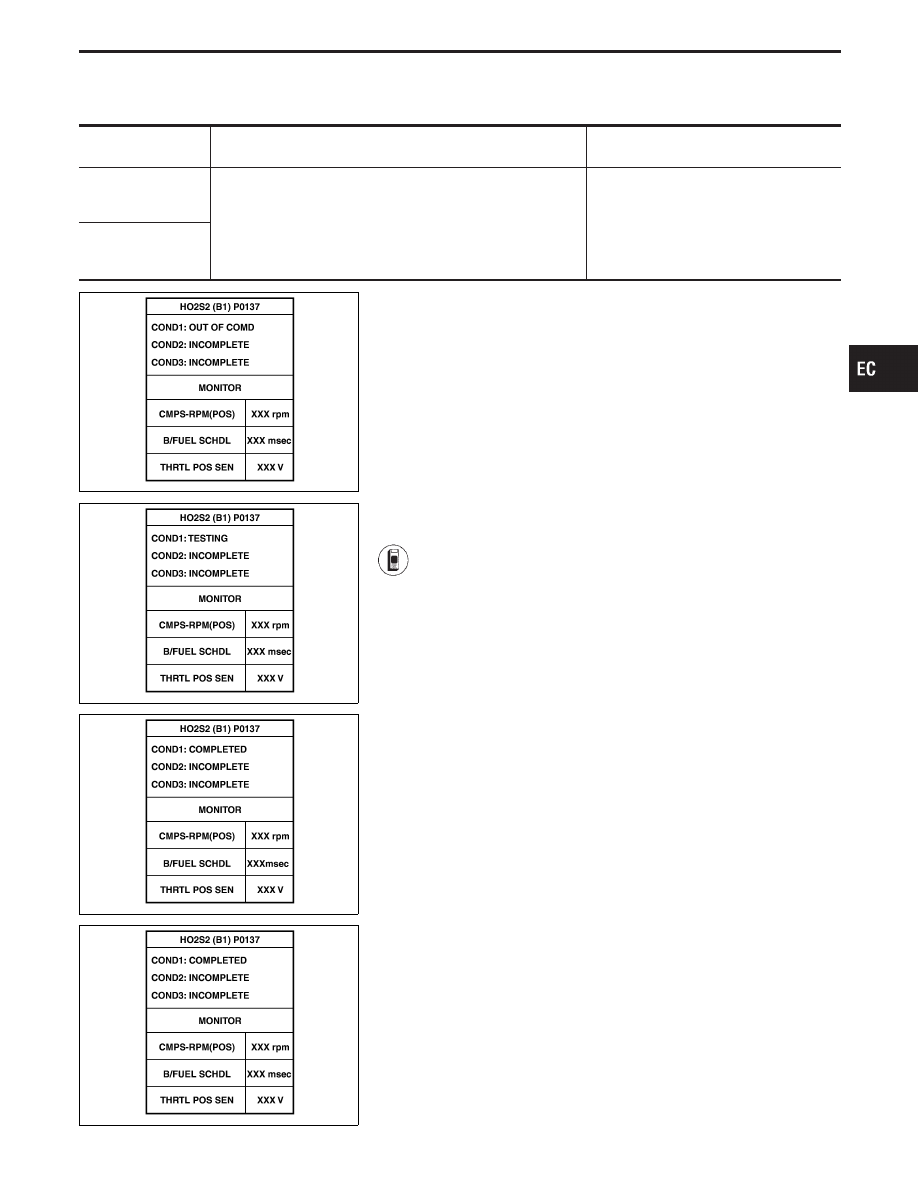
DIAGNOSTIC TROUBLE CODE CONFIRMATION
PROCEDURE
CAUTION:
Always drive vehicle at a safe speed.
NOTE:
I
“COMPLETED” will appear on CONSULT-II screen when all
tests “COND1”, “COND2” and “COND3” are completed.
I
If “DIAGNOSTIC TROUBLE CODE CONFIRMATION PRO-
CEDURE” has been previously conducted, always turn
ignition switch “OFF” and wait at least 5 seconds before
conducting the next test.
TESTING CONDITION:
Never stop engine during this test. If the engine is stopped,
reperform this test from step 2).
Procedure for COND1
1) Start engine and warm it up to normal operating tem-
perature.
2) Turn ignition switch “OFF” and wait at least 5 seconds.
3) Turn ignition switch “ON” and select “HO2S2 (B1)
P0137, (B2) P0157” of “HO2S2” in “DTC WORK SUP-
PORT” mode with CONSULT-II.
4) Touch “START”.
5) Start engine (TCS switch “OFF”) and let it idle for at
least 30 seconds.
6) Rev engine up to 2,000 rpm 2 or 3 times quickly under
no load.
If “COMPLETED” appears on CONSULT-II screen, go
to step 10).
If “COMPLETED” does not appear on CONSULT-II
screen, go to the following step.
7) Drive vehicle at a speed of more than 70 km/h (43 MPH)
for 2 consecutive minutes.
8) When the following conditions are met, “TESTING” will
be displayed at “COND1” on the CONSULT-II screen.
Maintain the conditions continuously until “TESTING”
changes to “COMPLETED” (It will take approximately
60 seconds.)
CMPS-RPM (POS): 1,200 - 2,500 rpm
Vehicle speed: 64 - 100 km/h (40 - 62 MPH)
B/FUEL SCHDL: 0.5 - 5.0 msec
Selector lever: Suitable position
NOTE:
I
If “TESTING” is not displayed after 5 minutes, retry
from step 2).
I
If “COMPLETED” already appears at “COND2” on
CONSULT-II screen before “Procedure for COND2”
is conducted, it is unnecessary to conduct step 9).
GI
MA
EM
LC
FE
AT
PD
FA
RA
BR
ST
RS
BT
HA
EL
IDX
TROUBLE DIAGNOSIS FOR DTC P0137 (B1), P0157 (B2)
Heated Oxygen Sensor 2 (Rear) (P0137: Bank
1), (P0157: Bank 2) (Min. Voltage Monitoring)
(Cont’d)
EC-211
SEF835Y
Procedure for COND2
9) While driving release accelerator pedal completely with
“OD” OFF from the above condition (step 8) until
“INCOMPLETE” at “COND2” on CONSULT-II screen
has turned to “COMPLETED”. (It will take approximately
4 seconds.)
I
If “TESTING” is not displayed after 5 minutes, retry
from step 2).
I
If “COMPLETED” already appears at “COND3” on
CONSULT-II screen before “Procedure for COND3”
is conducted, it is unnecessary to conduct step 10).
Procedure for COND3
10) Stop vehicle and let it idle until “INCOMPLETE” of
“COND3” on CONSULT-II screen has turned to “COM-
PLETED”. (It will take a maximum of approximately 6
minutes.)
11) Make sure that “OK” is displayed after touching “SELF-
DIAG RESULTS”. If “NG” is displayed, refer to “DIAG-
NOSTIC PROCEDURE”, EC-215.
SEF354WA
------------------------------------------------------------------------------------------------------------------------------------------------------------------------------------------------------------------------------------------------------ OR ------------------------------------------------------------------------------------------------------------------------------------------------------------------------------------------------------------------------------------------------------
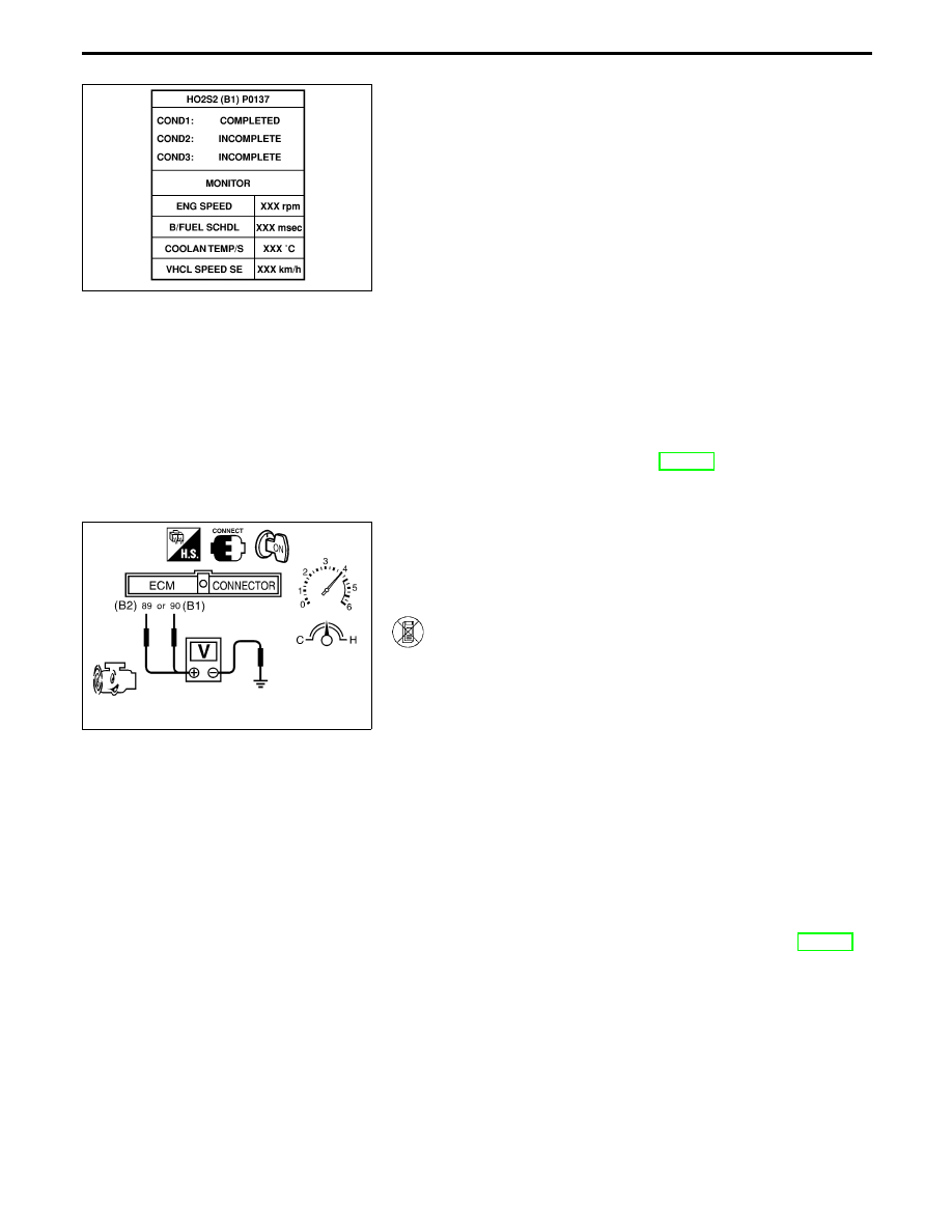
OVERALL FUNCTION CHECK
Use this procedure to check the overall function of the heated oxy-
gen sensor 2 (rear) circuit. During this check, a 1st trip DTC might
not be confirmed.
1) Start engine and drive vehicle at a speed of more than
70 km/h (43 MPH) for 2 consecutive minutes.
2) Stop vehicle with engine running.
3) Set voltmeter probes between ECM terminals
q
89
(B2),
q
90
(B1) (sensor signal) and ground.
4) Check the voltage when revving engine up to 4,000 rpm
under no load at least 10 times.
(depress and release accelerator pedal as soon as pos-
sible)
The voltage should be below 0.43V at least once
during this procedure.
If the voltage can be confirmed in step 4, step 5 is
not necessary.
5) Keep vehicle at idling for 10 minutes, then check the
voltage. Or check the voltage when coasting from 80
km/h (50 MPH) in D position with “OD” OFF.
The voltage should be below 0.43V at least once
during this procedure.
6) If NG, go to “DIAGNOSTIC PROCEDURE”, EC-215.
TROUBLE DIAGNOSIS FOR DTC P0137 (B1), P0157 (B2)
Heated Oxygen Sensor 2 (Rear) (P0137: Bank
1), (P0157: Bank 2) (Min. Voltage Monitoring)
(Cont’d)
EC-212
Нет комментариевНе стесняйтесь поделиться с нами вашим ценным мнением.
Текст