Infiniti Q45 (FY33). Manual — part 159
SEF152P
COMPONENT INSPECTION
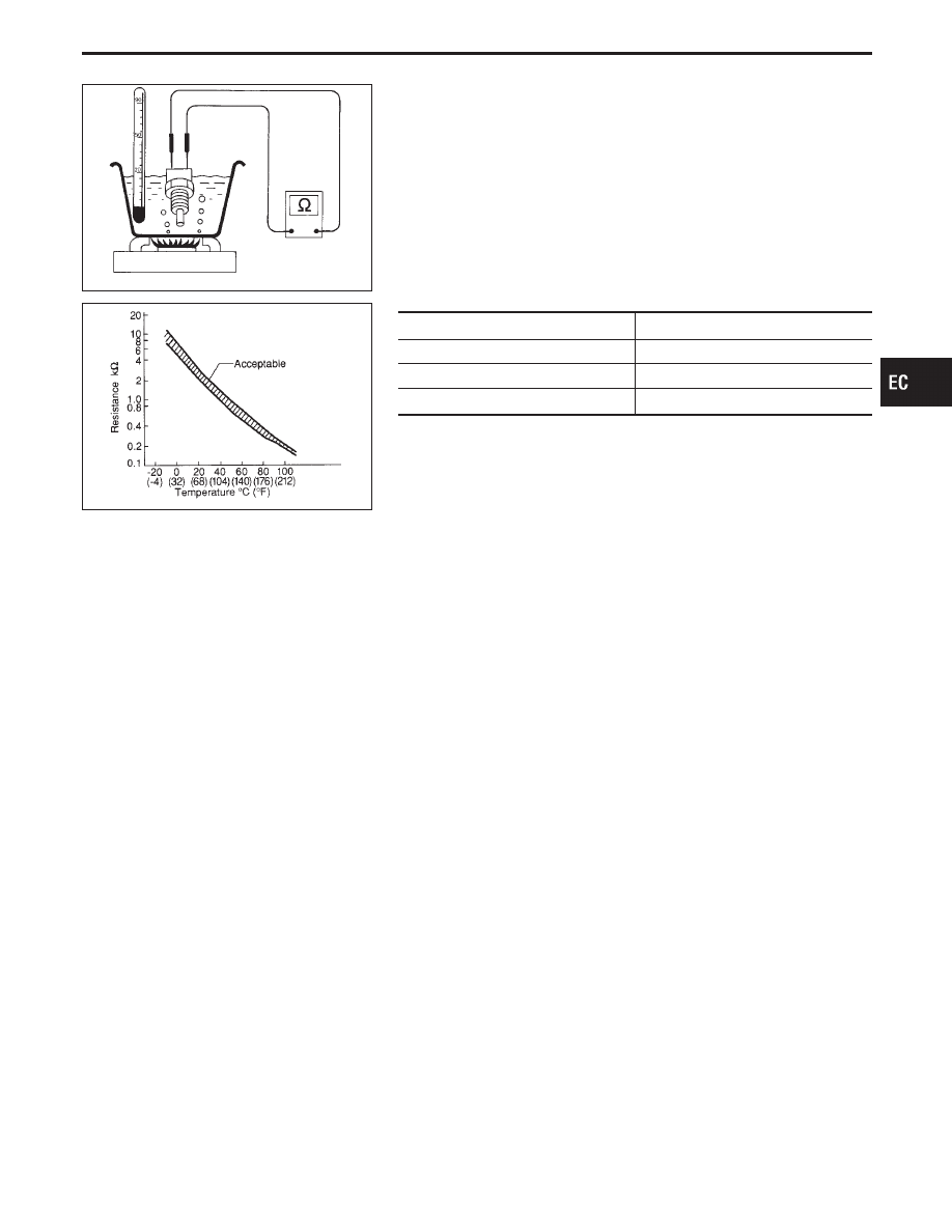
Engine coolant temperature sensor
Check resistance as shown in the figure.
SEF012P
Temperature °C (°F)
Resistance k
Ω
20 (68)
2.1 - 2.9
50 (122)
0.68 - 1.00
90 (194)
0.236 - 0.260
If NG, replace engine coolant temperature sensor.
GI
MA
EM
LC
FE
AT
PD
FA
RA
BR
ST
RS
BT
HA
EL
IDX
TROUBLE DIAGNOSIS FOR DTC P0125
Engine Coolant Temperature (ECT) Sensor
(Cont’d)
EC-165
SEF463R
Heated Oxygen Sensor 1 (Front) (P0130: Bank
1), (P0150: Bank 2) (Circuit)
SEF288D
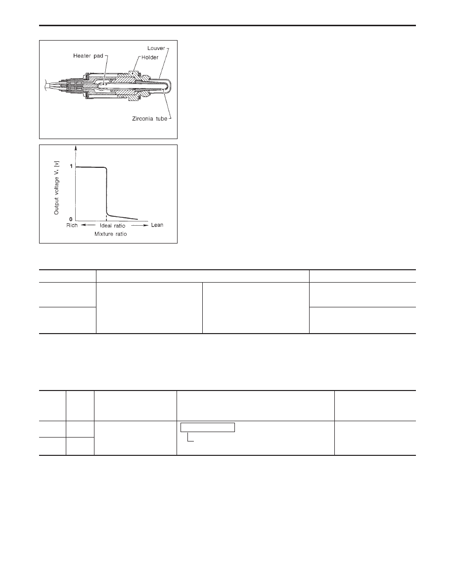
COMPONENT DESCRIPTION
The heated oxygen sensor 1 (front) is placed into the exhaust
manifold. It detects the amount of oxygen in the exhaust gas com-
pared to the outside air. The heated oxygen sensor 1 (front) has a
closed-end tube made of ceramic zirconia. The zirconia generates
voltage from approximately 1V in richer conditions to 0V in leaner
conditions. The heated oxygen sensor 1 (front) signal is sent to the
ECM. The ECM adjusts the injection pulse duration to achieve the
ideal air-fuel ratio. The ideal air-fuel ratio occurs near the radical
change from 1V to 0V.
CONSULT-II REFERENCE VALUE IN DATA MONITOR MODE
Specification data are reference values.
MONITOR ITEM
CONDITION
SPECIFICATION
HO2S1 (B1)
HO2S1 (B2)
I
Engine: After warming up
Maintaining engine speed at 2,000 rpm
0 - 0.3V
)
0.6 - 1.0V
HO2S1 MNTR (B1)
HO2S1 MNTR (B2)
LEAN
)
RICH
Changes more than 5 times
during 10 seconds.
ECM TERMINALS AND REFERENCE VALUE
Specification data are reference values, and are measured between each terminal and ground.
CAUTION:
Do not use ECM ground terminals when measuring voltage. Doing so may result in damage to the
ECM’s transistor. Use a ground other than ECM terminals such as the body ground.
TER-
MINAL
NO.
WIRE
COLOR
ITEM
CONDITION
DATA
(DC voltage)
82 (B2)
R
Heated oxygen sensors 1
(front)
Engine is running.
After warming up to normal operating tempera-
ture and engine speed is 2,000 rpm.
0 - Approximately 1.0V
(periodically change)
83 (B1)
W
TROUBLE DIAGNOSIS FOR DTC P0130 (B1), P0150 (B2)
EC-166
SEF237U
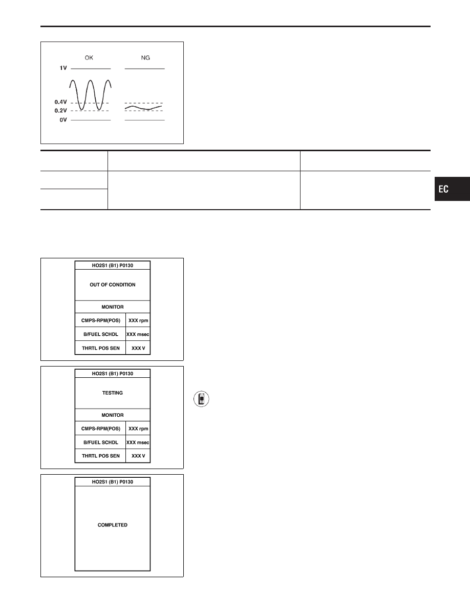
ON BOARD DIAGNOSIS LOGIC
Under the condition in which the heated oxygen sensor 1 (front)
signal is not input, the ECM circuits will read a continuous approxi-
mately 0.3V. Therefore, for this diagnosis, the time that output
voltage is within 200 to 400 mV range is monitored, and the diag-
nosis checks that this time is not inordinately long.
Diagnostic Trouble
Code No.
Malfunction is detected when ...
Check Items
(Possible Cause)
P0130, 0303
(Bank 1)
I
The voltage from the sensor is constantly approx. 0.3V.
I
Harness or connectors
(The sensor circuit is open or shorted.)
I
Heated oxygen sensor 1 (front)
P0150, 0503
(Bank 2)
SEF979Z
SEF980Z
SEF645Y
DIAGNOSTIC TROUBLE CODE CONFIRMATION
PROCEDURE
CAUTION:
Always drive vehicle at a safe speed.
NOTE:
I
If “DIAGNOSTIC TROUBLE CODE CONFIRMATION PRO-
CEDURE” has been previously conducted, always turn
ignition switch “OFF” and wait at least 5 seconds before
conducting the next test.
TESTING CONDITION:
I
Always drive vehicle at temperature of more than −10°C
(14°F).
I
Before performing the following procedure, confirm that
battery voltage is more than 11V at idle.
1) Start engine and warm it up to normal operating tem-
perature.
2) Stop engine and wait at least 5 seconds.
3) Turn ignition switch “ON” and select “HO2S1 (B1)
P0130, (B2) (P0150)” of “HO2S1” in “DTC WORK SUP-
PORT” mode with CONSULT-II.
4) Touch “START”.
5) Start engine (TCS switch “OFF”) and let it idle for at
least 3 minutes.
NOTE:
Never raise engine speed above 3,200 rpm after this
step. If the engine speed limit is exceeded, return to
step 5).
6) When the following conditions are met, “TESTING” will
be displayed on the CONSULT-II screen. Maintain the
conditions continuously until “TESTING” changes to
“COMPLETED”. (It will take approximately 10 to 60 sec-
onds.)
CMPS-RPM (POS): 1,600 - 2,200 rpm
Vehicle speed: More than 70 km/h (43 MPH)
GI
MA
EM
LC
FE
AT
PD
FA
RA
BR
ST
RS
BT
HA
EL
IDX
TROUBLE DIAGNOSIS FOR DTC P0130 (B1), P0150 (B2)
Heated Oxygen Sensor 1 (Front) (P0130: Bank
1), (P0150: Bank 2) (Circuit) (Cont’d)
EC-167
B/FUEL SCHDL: 1.4 - 5 msec
Selector lever: Suitable position
If “TESTING” is not displayed after 5 minutes, retry
from step 2).
7) Make sure that “OK” is displayed after touching “SELF-
DIAG RESULTS”. If “NG” is displayed, refer to “DIAG-
NOSTIC PROCEDURE”, EC-171.
During this test, P1148 and P1168 may be stored in
ECM.
SEF353WA
------------------------------------------------------------------------------------------------------------------------------------------------------------------------------------------------------------------------------------------------------ OR ------------------------------------------------------------------------------------------------------------------------------------------------------------------------------------------------------------------------------------------------------
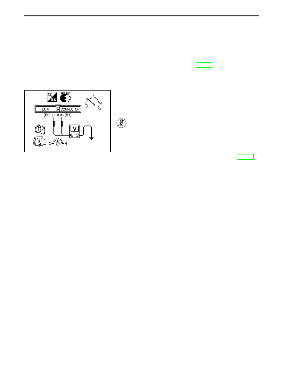
OVERALL FUNCTION CHECK
Use this procedure to check the overall function of the heated oxy-
gen sensor 1 (front) circuit. During this check, a 1st trip DTC might
not be confirmed.
1) Start engine and warm it up to normal operating tem-
perature.
2) Set voltmeter probes between ECM terminal
q
82
(B2),
q
83
(B1) (sensor signal) and ground.
3) Check the following with engine speed held at 2,000
rpm constant under no load.
I
The voltage does not remain in the range of 0.2 - 0.4V.
4) If NG, go to “DIAGNOSTIC PROCEDURE”, EC-171.
TROUBLE DIAGNOSIS FOR DTC P0130 (B1), P0150 (B2)
Heated Oxygen Sensor 1 (Front) (P0130: Bank
1), (P0150: Bank 2) (Circuit) (Cont’d)
EC-168
Нет комментариевНе стесняйтесь поделиться с нами вашим ценным мнением.
Текст