Infiniti EX37. Transaxle and Transmission (2013 year). Manual — part 18

TRANSMISSION ASSEMBLY
TM-273
< UNIT DISASSEMBLY AND ASSEMBLY >
[7AT: RE7R01A]
C
E
F
G
H
I
J
K
L
M
A
B
TM
N
O
P
74. Pour ATF into torque converter.
• Approximately 2 liter (2-1/8 US qt, 1-3/4 Imp qt) of ATF is
required for a new torque converter.
• When reusing old torque converter, add the same amount
of ATF as was drained.
75. Install torque converter while aligning notches of torque con-
verter with notches of oil pump.
CAUTION:
Install torque converter while rotating it.
76. Measure dimension (A) to make sure that torque converter is in
proper position.
Inspection
INFOID:0000000008285938
INSPECTION AFTER DISASSEMBLY
Oil Pan
Check foreign materials in oil pan to help determine causes of mal-
function. If the ATF is very dark, smells burned, or contains foreign
particles, the frictional material (clutches, band) may need replace-
ment. A tacky film that will not wipe clean indicates varnish build up.
Varnish can cause valves, servo, and clutches to stick and can
inhibit pump pressure.
• If frictional material is detected, replace radiator after repair of
A/T. Refer to
CO-13, "Removal and Installation"
.
Torque Converter
SAT428DA
SCIA5010E
B
: Scale
C
: Straightedge
Dimension (A)
: Refer to
.
JPDIA0042ZZ
SCIA5199E
2013 EX
-------------------------------------------------------------------------------------------------------------------------------------------------------------

TM-274
< UNIT DISASSEMBLY AND ASSEMBLY >
[7AT: RE7R01A]
TRANSMISSION ASSEMBLY
Check torque converter one-way clutch using a check tool as shown
at figure.
1.
Insert a check tool into the groove of bearing support built into
one-way clutch outer race.
2.
When fixing bearing support with a check tool, rotate one-way
clutch spline using a screwdriver.
3.
Make sure that inner race rotates clockwise only. If not, replace
torque converter assembly.
1st One-way Clutch
Check operation of 1st one-way clutch.
1.
Install 1st one-way clutch (1) to front brake hub (with under drive
carrier).
2.
Hold 1st one-way clutch.
3.
Check front brake hub for correct locking and unlocking direc-
tions. If necessary, replace 1st one-way clutch.
Under Drive Sun Gear
Check for deformation, fatigue or damage. If necessary, replace the under drive sun gear.
Mid Carrier Assembly
Check for deformation, fatigue or damage. If necessary, replace the mid carrier assembly.
Rear Carrier Assembly
Check for deformation, fatigue or damage. If necessary, replace the rear carrier assembly.
Reverse Brake Retaining Plate/Drive Plates/Driven Plates/Dish Plates
Check facing for burns, cracks or damage. If necessary, replace the damaged plate.
Front Brake Retaining Plates/Drive Plates/Driven Plate
Check facing for burns, cracks or damage. If necessary, replace the damaged plate.
Each Snap Ring
Check for deformation, fatigue or damage. If necessary, replace the snap ring.
Parking Actuator Support and Parking Pawl
SCIA3171E
: Unlocked
: Locked
JSDIA1713ZZ
2013 EX
-------------------------------------------------------------------------------------------------------------------------------------------------------------

TRANSMISSION ASSEMBLY
TM-275
< UNIT DISASSEMBLY AND ASSEMBLY >
[7AT: RE7R01A]
C
E
F
G
H
I
J
K
L
M
A
B
TM
N
O
P
If the contact surface on parking actuator support (1) and parking
pawl (2) has excessive wear, abrasion, bend or any other damage,
replace the components.
JPDIA0034ZZ
2013 EX
-------------------------------------------------------------------------------------------------------------------------------------------------------------

TM-276
< UNIT DISASSEMBLY AND ASSEMBLY >
[7AT: RE7R01A]
OIL PUMP, 2346 BRAKE, FRONT BRAKE PISTON
OIL PUMP, 2346 BRAKE, FRONT BRAKE PISTON
Exploded View
INFOID:0000000008285939
Disassembly
INFOID:0000000008285940
1.
Remove snap ring (1) from oil pump assembly using a flat-
bladed screwdriver (A).
CAUTION:
• Be careful not to scratch oil pump cover and 2346 brake
retaining plate.
• Be careful not to damage snap ring.
1.
Oil pump housing oil seal
2.
Oil pump housing
3.
O-ring
4.
Oil pump cover
5.
O-ring
6.
D-ring
7.
D-ring
8.
Front brake piston
9.
Front brake spring retainer
10. Snap ring
11.
D-ring
12. D-ring
13. 2346 brake piston
14. 2346 brake spring retainer
15. Snap ring
16. Seal ring
17. 2346 brake dish plate
18. 2346 brake driven plate
19. 2346 brake drive plate
20. 2346 brake retaining plate
21. Snap ring
: Apply Genuine RTV silicone sealant or equivalent. Refer to
GI-22, "Recommended Chemical Products and Sealants"
Refer to
for symbols not described on the above.
JPDIA1089GB
JPDIA1090ZZ
2013 EX
-------------------------------------------------------------------------------------------------------------------------------------------------------------

OIL PUMP, 2346 BRAKE, FRONT BRAKE PISTON
TM-277
< UNIT DISASSEMBLY AND ASSEMBLY >
[7AT: RE7R01A]
C
E
F
G
H
I
J
K
L
M
A
B
TM
N
O
P
2.
Remove 2346 brake component part (retaining plate, drive
plate, driven plate and dish plate) (1) from oil pump assembly.
3.
Remove seal ring (1) from oil pump assembly.
4.
Set the clutch spring compressor [SST: KV31103800 (
—
)]
(A) on front brake spring retainer and remove snap ring (fixing
front brake spring retainer) (1) from oil pump assembly while
compressing return spring.
CAUTION:
Be careful not to expand snap ring excessively.
5.
Remove front brake spring retainer (1) from oil pump assembly.
6.
Set the clutch spring compressor [SST: KV31102400 (J-34285
and J-34285-87)] (A) on 2346 brake spring retainer and remove
snap ring (fixing 2346 brake spring retainer) (1) from oil pump
assembly while compressing return spring.
CAUTION:
Be careful not to expand snap ring excessively.
JPDIA1091ZZ
JPDIA1092ZZ
JSDIA1729ZZ
JPDIA1094ZZ
B
: Press
JSDIA1730ZZ
2013 EX
-------------------------------------------------------------------------------------------------------------------------------------------------------------

TM-278
< UNIT DISASSEMBLY AND ASSEMBLY >
[7AT: RE7R01A]
OIL PUMP, 2346 BRAKE, FRONT BRAKE PISTON
7.
Remove 2346 brake spring retainer (1) from oil pump assembly.
8.
Remove front brake piston (1) from oil pump assembly with
compressed air. Refer to
.
CAUTION:
Care should be taken not to abruptly blow air. It makes pis-
ton incline, as the result, it becomes hard to disassemble
the piston.
9.
Remove D-ring (inner) (1) and D-ring (outer) (2) from front brake
piston.
JPDIA1096ZZ
A
: Front brake pressure hole
JPDIA1097ZZ
JPDIA1098ZZ
2013 EX
-------------------------------------------------------------------------------------------------------------------------------------------------------------

OIL PUMP, 2346 BRAKE, FRONT BRAKE PISTON
TM-279
< UNIT DISASSEMBLY AND ASSEMBLY >
[7AT: RE7R01A]
C
E
F
G
H
I
J
K
L
M
A
B
TM
N
O
P
10. Remove 2346 brake piston (1) from oil pump assembly with
compressed air. Refer to
.
CAUTION:
Care should be taken not to abruptly blow air. It makes pis-
ton incline, as the result, it becomes hard to disassemble
the piston.
11. Remove D-ring (large) (1) and D-ring (small) (2) from 2346
brake piston.
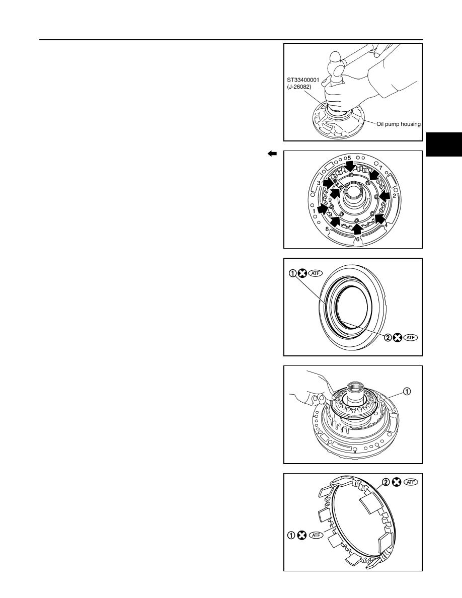
12. loosen bolts (
) in numerical order shown in the figure and
remove oil pump housing from oil pump cover.
13. Remove oil pump housing oil seal using a flat-bladed screw-
driver.
CAUTION:
Be careful not to scratch oil pump housing.
A
: 2346 brake pressure hole
JPDIA1099ZZ
JPDIA1100ZZ
JPDIA1101ZZ
SCIA2840E
2013 EX
-------------------------------------------------------------------------------------------------------------------------------------------------------------

TM-280
< UNIT DISASSEMBLY AND ASSEMBLY >
[7AT: RE7R01A]
OIL PUMP, 2346 BRAKE, FRONT BRAKE PISTON
14. Remove O-ring from oil pump housing.
15. Remove O-ring (1) from oil pump cover.
Assembly
INFOID:0000000008285941
1.
Install O-ring (1) to oil pump cover.
2.
Install O-ring to oil pump housing.
SCIA2841E
JPDIA1102ZZ
JPDIA1102ZZ
SCIA2841E
2013 EX
-------------------------------------------------------------------------------------------------------------------------------------------------------------
OIL PUMP, 2346 BRAKE, FRONT BRAKE PISTON
TM-281
< UNIT DISASSEMBLY AND ASSEMBLY >
[7AT: RE7R01A]
C
E
F
G
H
I
J
K
L
M
A
B
TM
N
O
P
3.
Using the drift (SST), install oil pump housing oil seal to the oil
pump housing until it is flush.
CAUTION:
• Never reuse oil seal.
• Apply ATF to oil seal.
4.
Install oil pump housing to oil pump cover and tighten bolts (
)
to the specified torque in numerical order shown in the figure
after temporarily tightening them.
5.
Install D-ring (large) (1) and D-ring (small) (2) to 2346 brake pis-
ton.
6.
Install 2346 brake piston (1) to oil pump assembly.
7.
Install D-ring (inner) (1) and D-ring (outer) (2) to front brake pis-
ton.
SCIA5313E
JPDIA1101ZZ
JPDIA1100ZZ
JSDIA1722ZZ
JPDIA1098ZZ
2013 EX
-------------------------------------------------------------------------------------------------------------------------------------------------------------

TM-282
< UNIT DISASSEMBLY AND ASSEMBLY >
[7AT: RE7R01A]
OIL PUMP, 2346 BRAKE, FRONT BRAKE PISTON
8.
Install front brake piston (1) to oil pump assembly.
9.
Install 2346 brake spring retainer (1) to oil pump assembly.
10. Set the clutch spring compressor [SST: KV31102400 (J-34285
and J-34285-87)] (A) on 2346 brake spring retainer and install
snap ring (fixing 2346 brake spring retainer) (1) to oil pump
assembly while compressing return spring.
CAUTION:
Be careful not to expand snap ring excessively.
11. Install front brake spring retainer (1) to oil pump assembly.
12. Set the clutch spring compressor [SST: KV31103800 (
—
)]
(A) on front brake spring retainer and install snap ring (fixing
front brake spring retainer) (1) to oil pump assembly while com-
pressing return spring.
CAUTION:
Be careful not to expand snap ring excessively.
JSDIA1723ZZ
JPDIA1096ZZ
B
: Press
JSDIA1730ZZ
JPDIA1094ZZ
JSDIA1729ZZ
2013 EX
-------------------------------------------------------------------------------------------------------------------------------------------------------------

OIL PUMP, 2346 BRAKE, FRONT BRAKE PISTON
TM-283
< UNIT DISASSEMBLY AND ASSEMBLY >
[7AT: RE7R01A]
C
E
F
G
H
I
J
K
L
M
A
B
TM
N
O
P
13. Install seal ring (1) to oil pump assembly.
14. Install 2346 brake component part (retaining plate, drive plates,
driven plates, dish plate and snap ring) to oil pump assembly.
CAUTION:
Check the order of plates.
15. Install snap ring (1) from oil pump assembly using a flat-bladed
screwdriver (A).
CAUTION:
• Be careful not to scratch oil pump cover and 2346 brake
retaining plate.
• Be careful not to damage snap ring.
• Never install snap ring mating part (A) to the clearance
groove [(B) shown in the figure] of oil pump cover.
Inspection and Adjustment
INFOID:0000000008285942
INSPECTION AFTER DISASSEMBLY
Each Snap Ring
Check for deformation, fatigue or damage. If necessary, replace snap ring.
Each Spring Retainer
Check for deformation, fatigue or damage. If necessary, replace spring retainer.
2346 Brake Retaining Plate/Drive Plates/Driven Plates/Dish Plate
JPDIA1092ZZ
1
: Dish plate
2
: Driven plate (four pieces)
3
: Drive plate (four pieces)
4
: Retaining plate
5
: Snap ring
JPDIA1152ZZ
JPDIA1090ZZ
JSDIA1724ZZ
2013 EX
-------------------------------------------------------------------------------------------------------------------------------------------------------------

TM-284
< UNIT DISASSEMBLY AND ASSEMBLY >
[7AT: RE7R01A]
OIL PUMP, 2346 BRAKE, FRONT BRAKE PISTON
Check facing for burns, cracks or damage. If necessary, replace the damaged plate.
ADJUSTMENT AFTER ASSEMBLY
2346 Brake Clearance
Set a dial indicator (A) as shown in the figure. Blow air into 2346
brake oil pressure hole (B), and measure 2346 brake clearance. If
clearance is outside the specified value, adjust clearance by select-
ing an appropriate snap ring (1). Refer to
.
CAUTION:
Never exceed the specified air pressure value.
Air pressure
: 300 kPa (3.06 kg/cm
2
, 43.5 psi)
2346 brake
clearance
: Refer to
JPDIA1148ZZ
2013 EX
-------------------------------------------------------------------------------------------------------------------------------------------------------------
UNDER DRIVE CARRIER, FRONT BRAKE HUB
TM-285
< UNIT DISASSEMBLY AND ASSEMBLY >
[7AT: RE7R01A]
C
E
F
G
H
I
J
K
L
M
A
B
TM
N
O
P
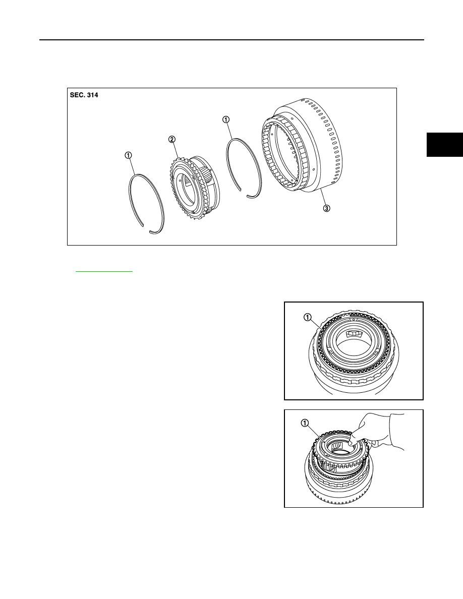
UNDER DRIVE CARRIER, FRONT BRAKE HUB
Exploded View
INFOID:0000000008285943
Disassembly
INFOID:0000000008285944
1.
Remove snap ring (1) from front brake hub using a flat-bladed
screwdriver.
CAUTION:
• Be careful not to scratch front brake hub and under drive
carrier assembly.
• Be careful not to damage snap ring.
2.
Remove under drive carrier assembly (1) from front brake hub.
1.
Snap ring
2.
Under drive carrier assembly
3.
Front brake hub
Refer to
JPDIA1127ZZ
JPDIA1128ZZ
JPDIA1129ZZ
2013 EX
-------------------------------------------------------------------------------------------------------------------------------------------------------------
TM-286
< UNIT DISASSEMBLY AND ASSEMBLY >
[7AT: RE7R01A]
UNDER DRIVE CARRIER, FRONT BRAKE HUB
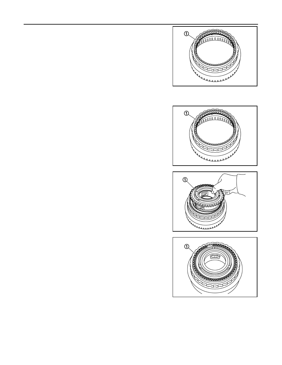
3.
Remove snap ring (1) from front brake hub using a flat-bladed
screwdriver.
CAUTION:
• Be careful not to scratch front brake hub.
• Be careful not to damage snap ring.
Assembly
INFOID:0000000008285945
1.
Install snap ring (1) to front brake hub.
CAUTION:
Be careful not to damage snap ring.
2.
Install under drive carrier assembly (1) to front brake hub.
3.
Install snap ring (1) to front brake hub using a flat-bladed screw-
driver.
CAUTION:
• Be careful not to scratch front brake hub.
• Be careful not to damage snap ring.
Inspection
INFOID:0000000008285946
INSPECTION AFTER DISASSEMBLY
• Each Snap Ring
Check for deformation, fatigue or damage. If necessary, replace snap ring.
• Under Drive Carrier Assembly
Check for deformation, fatigue or damage. If necessary, replace under drive carrier assembly.
• Front Brake Hub
JPDIA1130ZZ
JPDIA1130ZZ
JPDIA1129ZZ
JPDIA1128ZZ
2013 EX
-------------------------------------------------------------------------------------------------------------------------------------------------------------
UNDER DRIVE CARRIER, FRONT BRAKE HUB
TM-287
< UNIT DISASSEMBLY AND ASSEMBLY >
[7AT: RE7R01A]
C
E
F
G
H
I
J
K
L
M
A
B
TM
N
O
P
Check for deformation, fatigue or damage. If necessary, replace front brake hub.
2013 EX
-------------------------------------------------------------------------------------------------------------------------------------------------------------
TM-288
< UNIT DISASSEMBLY AND ASSEMBLY >
[7AT: RE7R01A]
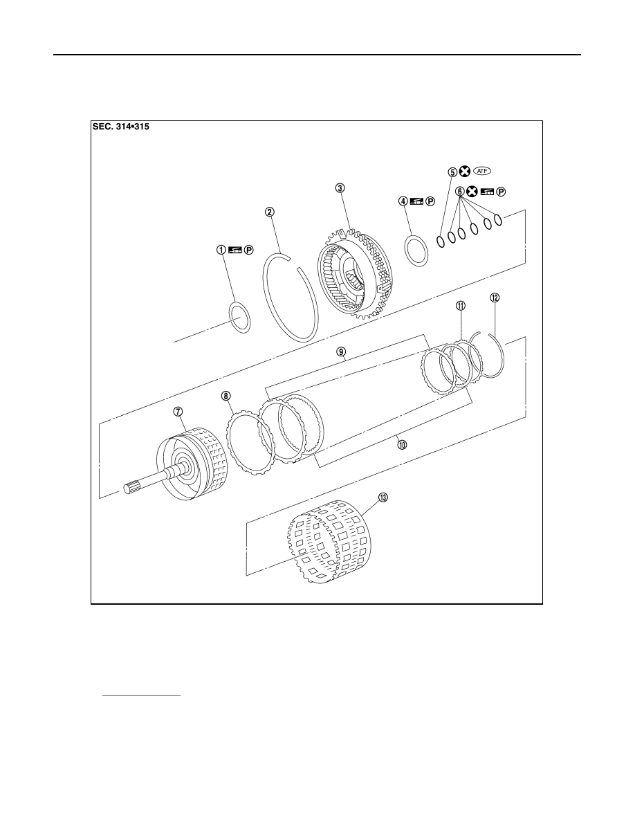
FRONT CARRIER, INPUT CLUTCH, REAR INTERNAL GEAR
FRONT CARRIER, INPUT CLUTCH, REAR INTERNAL GEAR
Exploded View
INFOID:0000000008285947
1.
Needle bearing
2.
Snap ring
3.
Front carrier assembly
4.
Needle bearing
5.
O-ring
6.
Seal ring
7.
Input clutch drum
8.
Input clutch dish plate
9.
Input clutch driven plate
10.
Input clutch drive plate
11.
Input clutch retaining plate
12. Snap ring
13.
Rear internal gear
Refer to
for symbols in the figure.
JPDIA1189ZZ
2013 EX
-------------------------------------------------------------------------------------------------------------------------------------------------------------
Нет комментариевНе стесняйтесь поделиться с нами вашим ценным мнением.
Текст