Infiniti EX37. Transaxle and Transmission (2013 year). Manual — part 13
PARKING COMPONENTS
TM-193
< REMOVAL AND INSTALLATION >
[7AT: RE7R01A]
C
E
F
G
H
I
J
K
L
M
A
B
TM
N
O
P
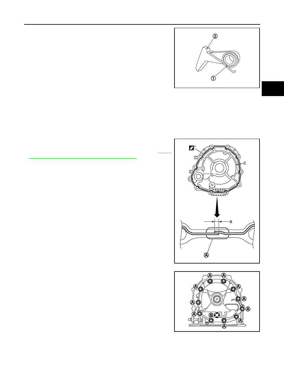
18. Remove return spring (1) from parking pawl (2).
INSTALLATION
Note the following, and install in the reverse order of removal.
CAUTION:
• Never reuse seal rings and drain plug gasket.
• Apply petroleum jelly to needle bearing and seal rings.
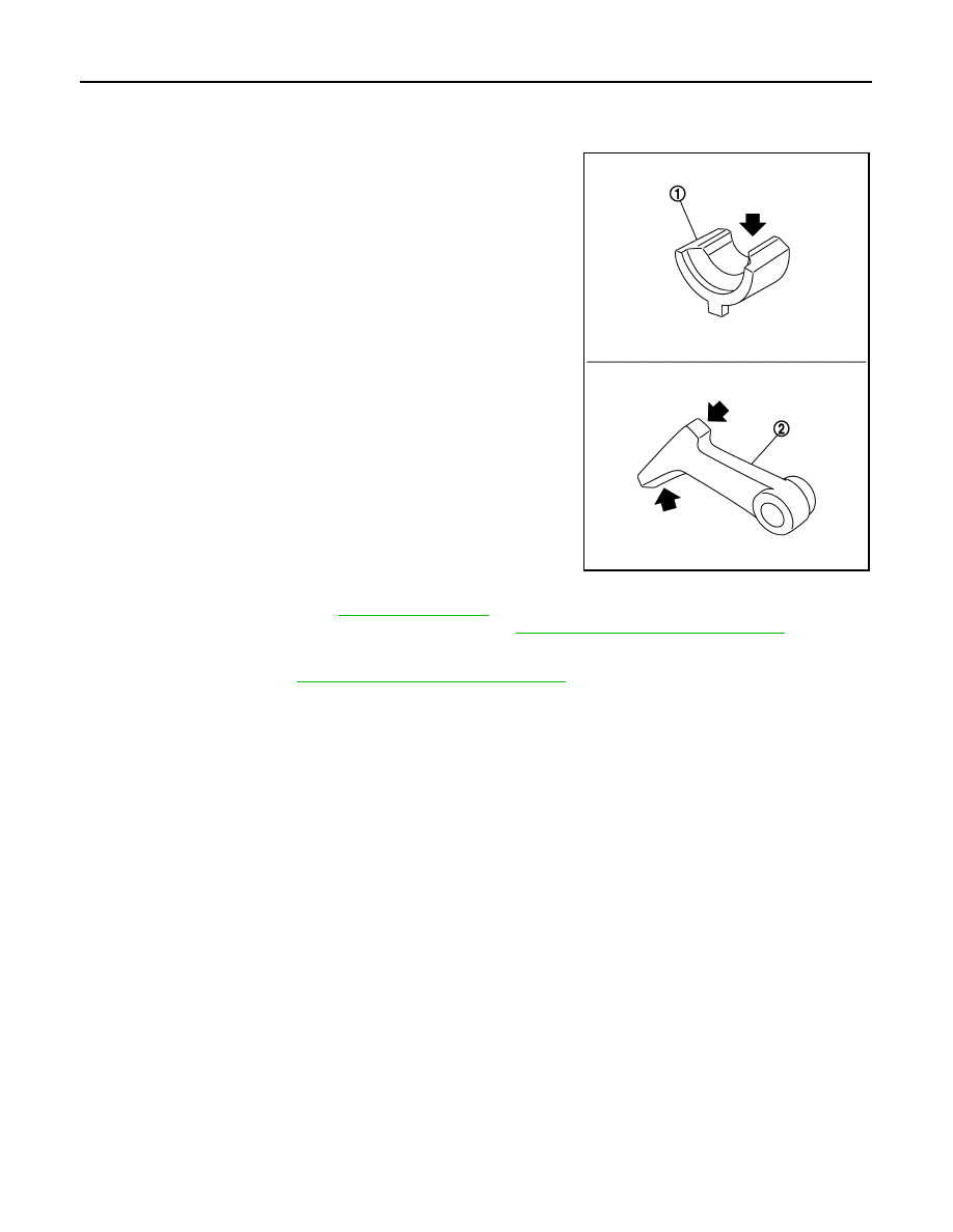
• Insert the tip of parking rod between the parking pawl and the parking actuator support when assem-
bling the rear extension assembly.
• Refer to the followings installing rear extension assembly.
- Apply recommended sealant to rear extension assembly as shown
in the figure.
Use Anaerobic Liquid Gasket or an equivalent. Refer to
"Recommended Chemical Products and Sealants"
.
CAUTION:
Completely remove all moisture, oil and old sealant, etc. from
transmission case and rear extension assembly mounting
surfaces.
- Tighten rear extension assembly bolts to the specified torque.
SCIA6180J
Sealant starting
point and end-
point (A)
: Start and finish point shall be in
the center of two bolts.
Overlap width of
sealant starting
point and end-
point (B)
: 3 – 5 mm (0.12 – 0.20 in)
Sealant width (C)
: 1.0 – 2.0 mm (0.04 – 0.08 in)
Sealant height (C)
: 0.4 – 1.0 mm (0.016 – 0.04 in)
JSDIA1855ZZ
A
: Bolt
B
: Self-sealing bolt
JPDIA1138ZZ
2013 EX
-------------------------------------------------------------------------------------------------------------------------------------------------------------
TM-194
< REMOVAL AND INSTALLATION >
[7AT: RE7R01A]
PARKING COMPONENTS
2WD : Inspection
INFOID:0000000008285906
INSPECTION AFTER REMOVAL
If the contact surface on parking actuator support (1), parking pawl
(2) and etc. has excessive wear, abrasion, bend, or any other dam-
age, replace the components.
INSPECTION AFTER INSTALLATION
• Check A/T fluid leakage. Refer to
.
• Check A/T positions after adjusting A/T positions. Refer to
TM-180, "Inspection and Adjustment"
.
ADJUSTMENT AFTER INSTALLATION
Adjust A/T positions. Refer to
TM-180, "Inspection and Adjustment"
JPDIA0034ZZ
2013 EX
-------------------------------------------------------------------------------------------------------------------------------------------------------------
REAR OIL SEAL
TM-195
< REMOVAL AND INSTALLATION >
[7AT: RE7R01A]
C
E
F
G
H
I
J
K
L
M
A
B
TM
N
O
P
REAR OIL SEAL
2WD
2WD : Exploded View
INFOID:0000000008285907
2WD : Removal and Installation
INFOID:0000000008285908
REMOVAL
1.
Separate propeller shaft assembly. Refer to
DLN-95, "Removal and Installation"
.
2.
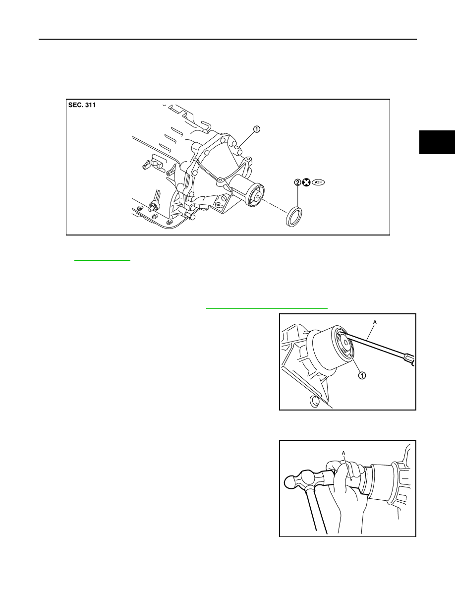
Remove rear oil seal (1) using a flat-bladed screwdriver (A).
CAUTION:
Be careful not to scratch rear extension assembly.
INSTALLATION
Note the following, and install in the reverse order of removal.
• As shown in the figure, use the drift [SST: ST33400001 (J-26082)]
(A) to drive rear oil seal into rear extension assembly until it is
flush.
CAUTION:
• Never reuse rear oil seal.
• Apply ATF to rear oil seal.
• Never incline rear oil seal.
1.
A/T assembly
2.
Rear oil seal
Refer to
JSDIA1725ZZ
JPDIA0037ZZ
JPDIA0039ZZ
2013 EX
-------------------------------------------------------------------------------------------------------------------------------------------------------------
TM-196
< REMOVAL AND INSTALLATION >
[7AT: RE7R01A]
REAR OIL SEAL
2WD : Inspection
INFOID:0000000008285909
INSPECTION AFTER INSTALLATION
Check A/T fluid leakage. Refer to
ADJUSTMENT AFTER INSTALLATION
Adjust A/T fluid level. Refer to
AWD
AWD : Exploded View
INFOID:0000000008285910
AWD : Removal and Installation
INFOID:0000000008285911
REMOVAL
1.
Remove transfer assembly from A/T assembly. Refer to
DLN-63, "Removal and Installation"
.
2.
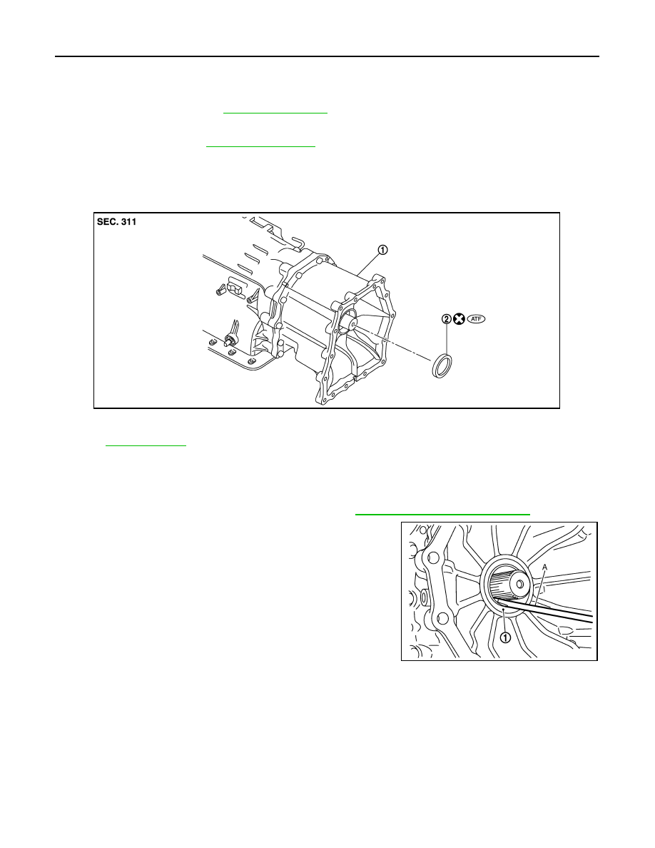
Remove rear oil seal (1) using a flat-bladed screwdriver (A).
CAUTION:
Be careful not to scratch adapter case assembly.
INSTALLATION
Note the following, and install in the reverse order of removal.
1.
A/T assembly
2.
Rear oil seal
Refer to
for symbols in the figure.
JSDIA1726ZZ
JPDIA0038ZZ
2013 EX
-------------------------------------------------------------------------------------------------------------------------------------------------------------

REAR OIL SEAL
TM-197
< REMOVAL AND INSTALLATION >
[7AT: RE7R01A]
C
E
F
G
H
I
J
K
L
M
A
B
TM
N
O
P
• As shown in the figure, use the drift [64 mm (2.52 in) dia. commer-
cial service tool] (A) to drive rear oil seal into adapter case assem-
bly until it is flush.
CAUTION:
• Never reuse rear oil seal.
• Apply ATF to rear oil seal.
• Never incline rear oil seal.
AWD : Inspection
INFOID:0000000008285912
INSPECTION AFTER INSTALLATION
Check A/T fluid leakage. Refer to
.
ADJUSTMENT AFTER INSTALLATION
Adjust A/T fluid level. Refer to
JPDIA0040ZZ
2013 EX
-------------------------------------------------------------------------------------------------------------------------------------------------------------

TM-198
< REMOVAL AND INSTALLATION >
[7AT: RE7R01A]
OUTPUT SPEED SENSOR
OUTPUT SPEED SENSOR
2WD
2WD : Exploded View
INFOID:0000000008285913
2WD : Removal and Installation
INFOID:0000000008285914
REMOVAL
1.
Disconnect the battery cable from the negative terminal.
2.
Drain ATF through drain plug.
3.
Remove exhaust front tube and center muffler with power tool. Refer to
EX-6, "Removal and Installation"
4.
Remove propeller shaft assembly. Refer to
DLN-95, "Removal and Installation"
.
5.
Remove control rod. Refer to
TM-184, "Removal and Installation"
6.
Remove exhaust mounting bracket. Refer to
EX-6, "Removal and Installation"
.
1.
A/T assembly
2.
Oil pan gasket
3.
Oil pan
4.
Clip
5.
Oil pan mounting bolt
6.
Overflow plug
7.
Drain plug
8.
Drain plug gasket
9.
Magnet
10.
Output speed sensor
11.
Self-sealing bolt
12.
Rear extension
*
: Apply Genuine Anaerobic Liquid Gasket or equivalent. Refer to
GI-22, "Recommended Chemical Products and Sealants"
.
Refer to
for symbols not described on the above.
JSDIA1953GB
2013 EX
-------------------------------------------------------------------------------------------------------------------------------------------------------------

OUTPUT SPEED SENSOR
TM-199
< REMOVAL AND INSTALLATION >
[7AT: RE7R01A]
C
E
F
G
H
I
J
K
L
M
A
B
TM
N
O
P
7.
Disconnect heated oxygen sensor 2 harness connectors (A).
8.
Remove heated oxygen sensor 2 harness (B) from clips (1).
9.
Remove bracket (2) from transmission assembly. Refer to
211, "2WD : Removal and Installation"
.
10. Remove clips (1).
11. Remove oil pan (2) and oil pan gasket.
12. Support A/T assembly with a transmission jack.
CAUTION:
When setting transmission jack, place wooden blocks to
prevent from damaging control valve & TCM and transmis-
sion case.
13. Remove rear engine mounting member with power tool. Refer to
14. Remove engine mounting insulator (rear). Refer to
15. Remove tightening bolts for rear extension assembly and trans-
mission case.
16. Tap rear extension assembly with a soft hammer (A).
: Vehicle front
: Bolt
SCIA8269E
: Vehicle front
: Oil pan mounting bolt
A
: Bolt
B
: Self-sealing bolt
JSDIA0793ZZ
JPDIA1138ZZ
JPDIA0027ZZ
2013 EX
-------------------------------------------------------------------------------------------------------------------------------------------------------------

TM-200
< REMOVAL AND INSTALLATION >
[7AT: RE7R01A]
OUTPUT SPEED SENSOR
17. Remove rear extension assembly (with needle bearing) from
transmission case.
18. Disconnect output speed sensor connector (A).
CAUTION:
Be careful not to damage connector
19. Disengage terminal clips (
).
20. Remove output speed sensor (1) from transmission case.
CAUTION:
• Never subject it to impact by dropping or hitting it.
• Never disassemble.
• Never allow metal filings, etc. to get on the sensor's front
edge magnetic area.
• Never place in an area affected by magnetism.
INSTALLATION
Note the following, and install in the reverse order removal.
CAUTION:
• Insert the tip of parking rod between the parking pole and the parking actuator support when assem-
bling the rear extension assembly.
• Never reuse drain plug gasket.
• Refer to the followings when installing output speed sensor.
CAUTION:
• Never subject it to impact by dropping or hitting it.
• Never disassemble.
• Never allow metal filings, etc. to get on the sensor's front edge magnetic area.
• Never place in an area affected by magnetism.
• Refer to the followings when installing rear extension assembly.
SCIA3431E
JPDIA1104ZZ
: Bolt
JSDIA1885ZZ
2013 EX
-------------------------------------------------------------------------------------------------------------------------------------------------------------

OUTPUT SPEED SENSOR
TM-201
< REMOVAL AND INSTALLATION >
[7AT: RE7R01A]
C
E
F
G
H
I
J
K
L
M
A
B
TM
N
O
P
- Apply recommended sealant to rear extension assembly as shown
in the figure.
Use Anaerobic Liquid Gasket or an equivalent. Refer to
"Recommended Chemical Products and Sealants"
.
CAUTION:
Completely remove all moisture, oil and old sealant, etc. from
transmission case and rear extension assembly mounting
surfaces.
- Tighten rear extension assembly bolts to the specified torque.
• Refer to the followings when installing oil pan (2) (with oil pan gas-
ket) and clips (1) to transmission case.
CAUTION:
• Never reuse oil pan gasket and oil pan mounting bolts.
• Install oil pan gasket in the direction to align hole position.
• Install it so that drain plug comes to the position as shown
in the figure.
• Be careful not to pinch harnesses.
• Completely remove all moisture, oil and old gasket, etc. from oil pan mounting surface.
Sealant starting
point and end-
point (A)
: Start and finish point shall be in
the center of two bolts.
Overlap width of
sealant starting
point and end-
point (B)
: 3 – 5 mm (0.12 – 0.20 in)
Sealant width (C)
: 1.0 – 2.0 mm (0.04 – 0.08 in)
Sealant height (C)
: 0.4 – 1.0 mm (0.016 – 0.04 in)
JSDIA1855ZZ
A
: Bolt
B
: Self-sealing bolt
JPDIA1138ZZ
: Vehicle front
: Oil pan mounting bolt
JSDIA0793ZZ
2013 EX
-------------------------------------------------------------------------------------------------------------------------------------------------------------

TM-202
< REMOVAL AND INSTALLATION >
[7AT: RE7R01A]
OUTPUT SPEED SENSOR
- Tighten oil pan mounting bolts to the specified torque in numerical
order shown in the figure after temporarily tightening them. Tighten
necessary oil pan mounting bolts with specified torque.
2WD : Inspection
INFOID:0000000008285915
INSPECTION AFTER REMOVAL
Check foreign materials in oil pan to help determine causes of mal-
function. If the ATF is very dark, smells burned, or contains foreign
particles, the frictional material (clutches, band) may need replace-
ment. A tacky film that will not wipe clean indicates varnish build up.
Varnish can cause valves, servo, and clutches to stick and can
inhibit pump pressure.
• If frictional material is detected, replace radiator after repair of
A/T. Refer to
CO-13, "Removal and Installation"
.
INSPECTION AFTER INSTALLATION
• Check A/T fluid leakage. Refer to
.
• Check A/T positions after adjusting A/T positions. Refer to
TM-180, "Inspection and Adjustment"
.
ADJUSTMENT AFTER INSTALLATION
Adjust A/T positions. Refer to
TM-180, "Inspection and Adjustment"
: Vehicle front
JSDIA0794ZZ
SCIA5199E
2013 EX
-------------------------------------------------------------------------------------------------------------------------------------------------------------

AIR BREATHER HOSE
TM-203
< REMOVAL AND INSTALLATION >
[7AT: RE7R01A]
C
E
F
G
H
I
J
K
L
M
A
B
TM
N
O
P
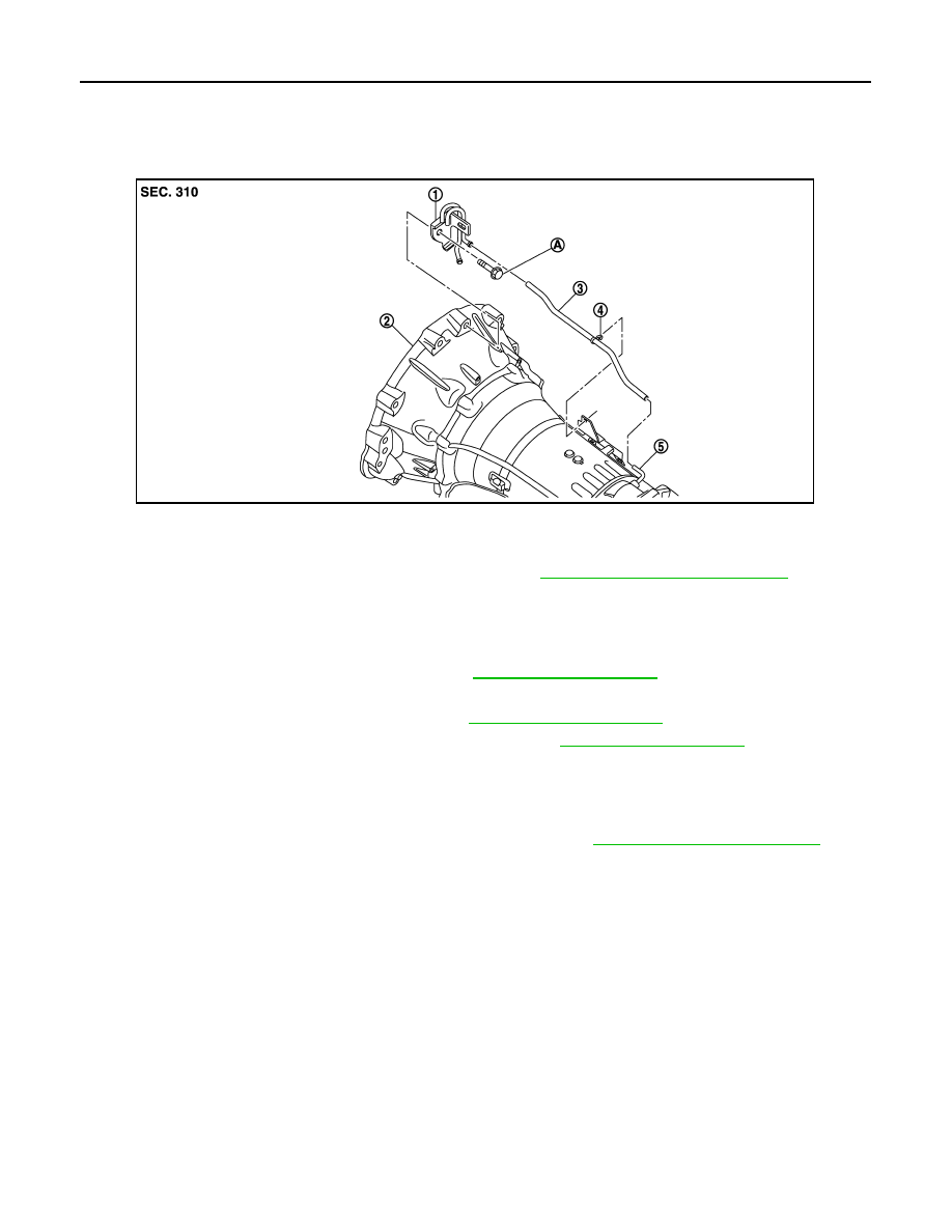
AIR BREATHER HOSE
2WD
2WD : Exploded View
INFOID:0000000008285916
2WD : Removal and Installation
INFOID:0000000008285917
REMOVAL
1.
Remove clips from brackets.
2.
Remove A/T air breather box from bracket.
3.
Remove A/T air breather box from A/T air breather hose.
4.
Remove A/T air breather hose.
5.
Separate propeller shaft assembly. Refer to
DLN-95, "Removal and Installation"
.
6.
Remove control rod from A/T shift selector assembly. Refer to
TM-182, "Removal and Installation"
7.
Support A/T assembly with a transmission jack.
CAUTION:
When setting the transmission jack, be careful not to allow it to collide against the drain plug and
overflow plug.
8.
Remove rear engine mounting member with a power tool. Refer to
9.
Remove bolt fixing A/T assembly to engine with a power tool.
10. Remove bracket.
INSTALLATION
Note the following, and install in the reverse order of removal.
CAUTION:
• When installing A/T air breather hose, be careful not to crushed or blocked by folding or bending the
hose.
• When inserting A/T air breather hose to A/T air breather tube, be sure to insert it fully until its end
reaches the radius curve end.
• When inserting A/T air breather hose to A/T air breather box, be sure to insert it fully until its end
reaches the stop.
• Install A/T air breather hose to A/T air breather box so that the paint mark is facing backward.
• Ensure clips are securely installed to brackets when installing air breather hose to brackets.
1.
Bracket
2.
A/T assembly
3.
A/T air breather tube
4.
Clip
5.
A/T air breather hose
6.
A/T air breather box
A.
Tightening must be done following the installation procedure. Refer to
TM-203, "2WD : Removal and Installation"
JSDIA1112ZZ
2013 EX
-------------------------------------------------------------------------------------------------------------------------------------------------------------
TM-204
< REMOVAL AND INSTALLATION >
[7AT: RE7R01A]
AIR BREATHER HOSE
AWD
AWD : Exploded View
INFOID:0000000008285918
AWD : Removal and Installation
INFOID:0000000008285919
REMOVAL
1.
Remove propeller shaft assembly (front). Refer to
2.
Remove A/T air breather hose.
3.
Remove propeller shaft assembly (rear). Refer to
4.
Remove control rod from A/T shift selector assembly. Refer to
5.
Support A/T assembly with a transmission jack.
CAUTION:
Be careful not to allow it to collide against the drain plug and overflow plug when setting the trans-
mission jack.
6.
Remove rear engine mounting member with a power tool. Refer to
.
7.
Remove bolt fixing A/T assembly to engine assembly with power tool.
8.
Remove air breather tube.
INSTALLATION
Note the following, and install in the reverse order of removal.
CAUTION:
• Never bend the air breather hose to prevent damage to the hose.
• Insert A/T air breather hose to A/T air breather tube all the way to the curve of the tube.
1.
Air breather tube
2.
A/T assembly
3.
A/T air breather hose
4.
Clip
5.
A/T air breather tube
A.
Tightening must be done following the installation procedure. Refer to
TM-214, "AWD : Removal and Installation"
JSDIA1412ZZ
2013 EX
-------------------------------------------------------------------------------------------------------------------------------------------------------------
AIR BREATHER HOSE
TM-205
< REMOVAL AND INSTALLATION >
[7AT: RE7R01A]
C
E
F
G
H
I
J
K
L
M
A
B
TM
N
O
P
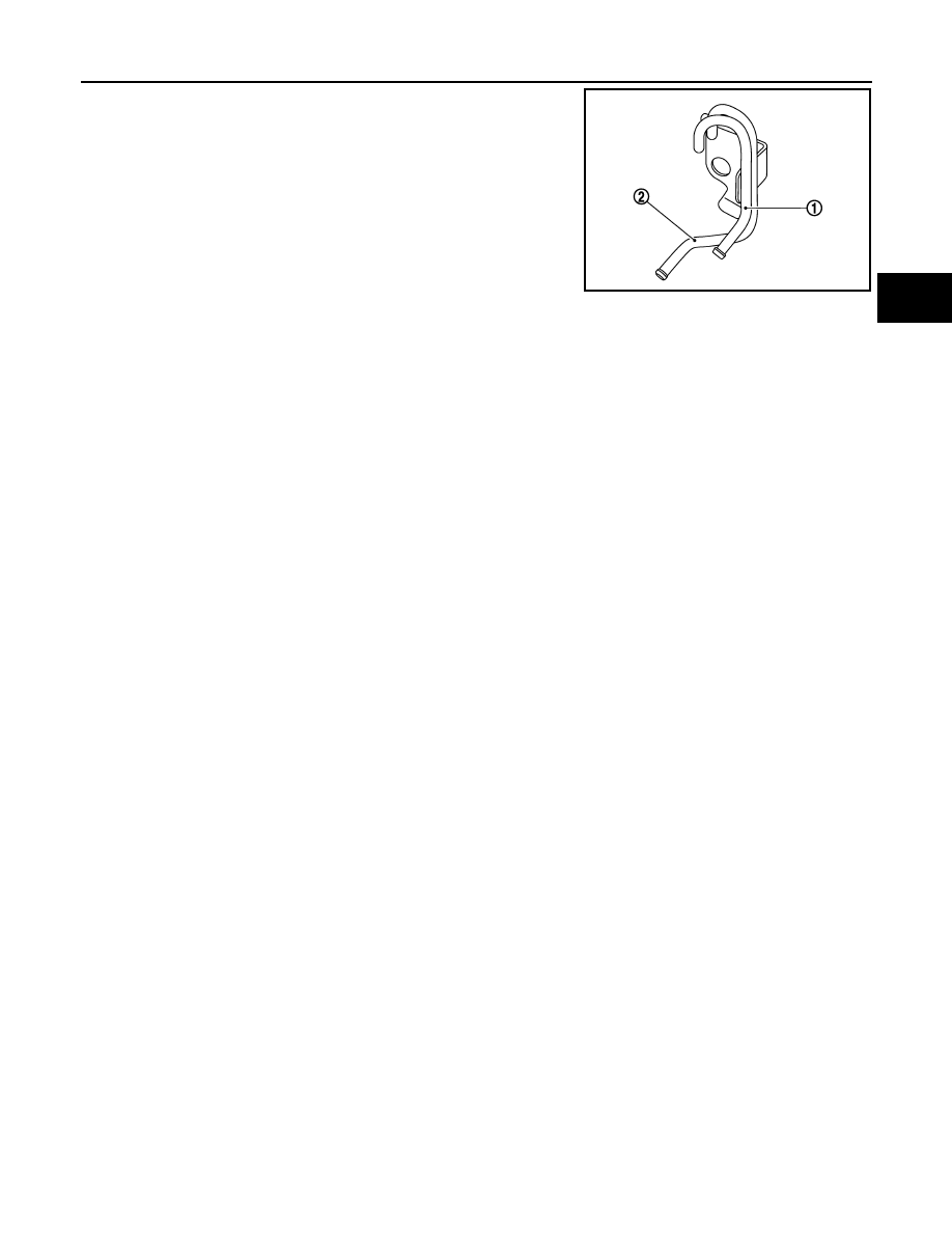
• When inserting A/T air breather hose to air breather tube (for
A/T) (1). be sure to insert it fully until its end reaches the
radius curve end.
• Install A/T air breather hose to air breather tube (for A/T) so
that the paint mark is facing upward.
• Securely install the clip to the brackets when installing A/T air
breather hose to the bracket.
2
: For transfer
JPDIA0931ZZ
2013 EX
-------------------------------------------------------------------------------------------------------------------------------------------------------------

TM-206
< REMOVAL AND INSTALLATION >
[7AT: RE7R01A]
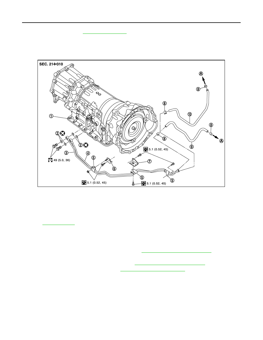
FLUID COOLER SYSTEM
FLUID COOLER SYSTEM
2WD
2WD : Exploded View
INFOID:0000000008285920
2WD : Removal and Installation
INFOID:0000000008285921
REMOVAL
1.
Remove engine lower cover with power tool. Refer to
EXT-31, "Removal and Installation"
2.
Remove A/T fluid cooler hose A and A/T fluid cooler hose B.
3.
Remove A/T fluid cooler tubes from A/T assembly and engine.
4.
Plug up opening such as the A/T fluid cooler tube hole.
5.
Remove A/T fluid cooler tubes from the vehicle.
CAUTION:
Be careful not to bend A/T fluid cooler tubes.
6.
Remove clips and bracket.
INSTALLATION
Note the following, and install in the reverse order of removal.
CAUTION:
Never reuse copper washer.
• Refer to the following when installing A/T fluid cooler hoses.
1.
A/T assembly
2.
Copper washer
3.
A/T fluid cooler tube
4.
A/T fluid cooler tube
5.
Clip
6.
Bracket
7.
Hose clamp
8.
A/T fluid cooler hose B
9.
A/T fluid cooler hose A
A.
To radiator
Refer to
for symbols in the figure.
JPDIA0856GB
2013 EX
-------------------------------------------------------------------------------------------------------------------------------------------------------------
FLUID COOLER SYSTEM
TM-207
< REMOVAL AND INSTALLATION >
[7AT: RE7R01A]
C
E
F
G
H
I
J
K
L
M
A
B
TM
N
O
P
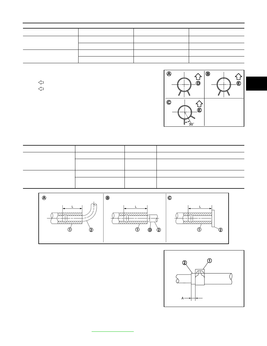
*: Refer to the illustrations for the specific position each hose clamp tab.
- The illustrations indicate the view from the hose ends.
- When installing hose clamps center line of each hose clamp tab
should be positioned as shown in the figure.
- Insert A/T fluid cooler hoses according to dimension “L” described below.
- Set hose clamps (1) at the both ends of A/T fluid cooler hoses (2)
with dimension “A” from the hose edge.
- Hose clamp should not interfere with the bulge of fluid cooler tube.
2WD : Inspection and Adjustment
INFOID:0000000008285922
INSPECTION AFTER INSTALLATION
Check A/T fluid leakage. Refer to
.
Hose name
Hose end
Paint mark
Position of hose clamp
*
A/T fluid cooler hose A
Radiator assembly side
Facing backward
A
A/T fluid cooler tube side
Facing downward
B
A/T fluid cooler hose B
Radiator assembly side
Facing downward
C
A/T fluid cooler tube side
Facing downward
B
D
: Vehicle front
E
: Vehicle upper
JSDIA0795ZZ
(1)
(2)
Tube type
Dimension “L”
A/T fluid cooler hose A
Radiator assembly side
A
End reaches the radius curve end.
A/T fluid cooler tube side
B
30 mm (1.18 in) [End reaches the 2-stage bulge
(D).]
A/T fluid cooler hose B
Radiator assembly side
C
Insert the hose until the hose touches the radiator.
A/T fluid cooler tube side
B
30 mm (1.18 in) [End reaches the 2-stage bulge
(D).]
JSDIA0882ZZ
Dimension “A”
: 5 – 9 mm (0.20 – 0.35 in)
SCIA8123E
2013 EX
-------------------------------------------------------------------------------------------------------------------------------------------------------------
TM-208
< REMOVAL AND INSTALLATION >
[7AT: RE7R01A]
FLUID COOLER SYSTEM
ADJUSTMENT AFTER INSTALLATION
Adjust A/T fluid level. Refer to
AWD
AWD : Exploded View
INFOID:0000000008285923
AWD : Removal and Installation
INFOID:0000000008285924
REMOVAL
1.
Remove engine lower cover with a power tool. Refer to
EXT-31, "Removal and Installation"
2.
Remove A/T fluid cooler hose A and A/T fluid cooler hose B.
3.
Remove control rod from A/T shift selector. Refer to
TM-182, "Removal and Installation"
4.
Remove exhaust mounting bracket. Refer to
EX-6, "Removal and Installation"
.
1.
A/T assembly
2.
Copper washer
3.
A/T fluid cooler tube
4.
A/T fluid cooler tube
5.
Clip
6.
Bracket
7.
Bracket
8.
Hose clamp
9.
A/T fluid cooler hose B
10. A/T fluid cooler hose A
A.
To radiator
Refer to
for symbols in the figure.
JPDIA0854GB
2013 EX
-------------------------------------------------------------------------------------------------------------------------------------------------------------
Нет комментариевНе стесняйтесь поделиться с нами вашим ценным мнением.
Текст