Infiniti EX37. Transaxle and Transmission (2013 year). Manual — part 5

DIAGNOSIS SYSTEM (TCM)
TM-65
< SYSTEM DESCRIPTION >
[7AT: RE7R01A]
C
E
F
G
H
I
J
K
L
M
A
B
TM
N
O
P
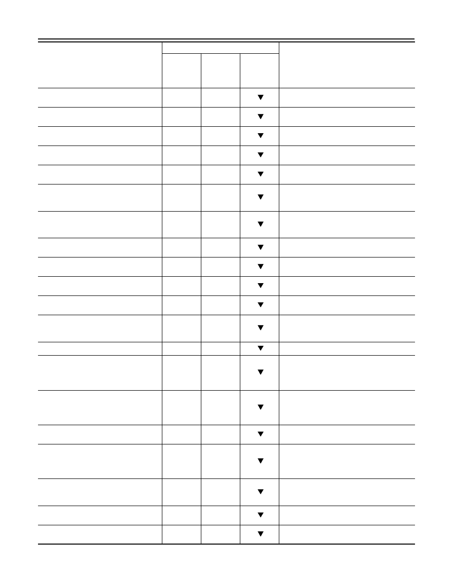
HLR/C SOL MON
(A)
—
—
Monitors the command current from TCM to the
high and low reverse clutch solenoid, and dis-
plays the monitor value.
I/C SOL MON
(A)
—
—
Monitors the command current from TCM to the
input clutch solenoid, and displays the monitor
value.
D/C SOL MON
(A)
—
—
Monitors the command current from TCM to the
direct clutch solenoid, and displays the monitor
value.
2346/B SOL MON
(A)
—
—
Monitors the command current from TCM to the
2346 brake solenoid, and displays the monitor
value.
GEAR RATIO
—
X
Displays the gear ratio calculated from input
speed and output speed.
ENGINE TORQUE
(Nm)
—
—
Displays the engine torque estimated value re-
ceived via CAN communication.
ENG TORQUE D
(Nm)
—
—
Displays the engine torque estimated value re-
flected the requested torque of each control unit
received via CAN communication.
INPUT TRQ S
(Nm)
—
—
Displays the input torque using for the oil pres-
sure calculation process of shift change control.
INPUT TRQ L/P
(Nm)
—
—
Displays the input torque using for the oil pres-
sure calculation process of line pressure con-
trol.
TRGT PRES L/P
(kPa, kg/cm
2
or psi)
—
—
Displays the target oil pressure value of torque
converter clutch solenoid valve calculated by
the oil pressure calculation process of lock-up
control.
TRGT PRES TCC
(kPa, kg/cm
2
or psi)
—
—
Displays the target oil pressure value of torque
converter clutch solenoid valve calculated by
the oil pressure calculation process of shift
change control.
TRGT PRES L/B
(kPa, kg/cm
2
or psi)
—
—
Displays the target oil pressure value of low
brake solenoid valve calculated by the oil pres-
sure calculation process of shift change control.
TRGT PRE FR/B
(kPa, kg/cm
2
or psi)
—
—
Displays the target oil pressure value of front
brake solenoid valve calculated by the oil pres-
sure calculation process of shift change control.
TRG PRE HLR/C
(kPa, kg/cm
2
or psi)
—
—
Displays the target oil pressure value of high
and low reverse clutch solenoid valve calculat-
ed by the oil pressure calculation process of
shift change control.
TRGT PRES I/C
(kPa, kg/cm
2
or psi)
—
—
Displays the target oil pressure value of input
clutch solenoid valve calculated by the oil pres-
sure calculation process of shift change control.
TRGT PRES D/C
(kPa, kg/cm
2
or psi)
—
—
Displays the target oil pressure value of direct
clutch solenoid valve calculated by the oil pres-
sure calculation process of shift change control.
TRG PRE 2346/B
(kPa, kg/cm
2
or psi)
—
—
Displays the target oil pressure value of 2346
brake solenoid valve calculated by the oil pres-
sure calculation process of shift change control.
SHIFT PATTERN
—
—
Displays the gear change data using the shift
pattern control.
Monitored item (Unit)
Monitor Item Selection
Remarks
ECU IN-
PUT SIG-
NALS
MAIN SIG-
NALS
SELEC-
TION
FROM
ITEM
2013 EX
-------------------------------------------------------------------------------------------------------------------------------------------------------------
TM-66
< SYSTEM DESCRIPTION >
[7AT: RE7R01A]
DIAGNOSIS SYSTEM (TCM)
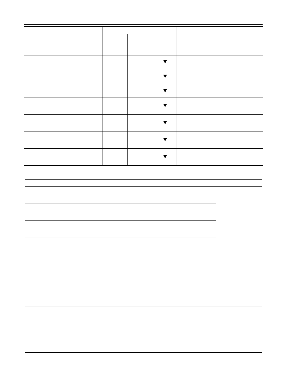
VEHICLE SPEED
(km/h or mph)
—
—
Displays the vehicle speed for control using the
control of TCM.
RANGE SW 4
(ON/OFF)
X
—
Displays the operation status of transmission
range switch 4.
RANGE SW 3
(ON/OFF)
X
—
Displays the operation status of transmission
range switch 3.
RANGE SW 2
(ON/OFF)
X
—
Displays the operation status of transmission
range switch 2.
RANGE SW 1
(ON/OFF)
X
—
Displays the operation status of transmission
range switch 1.
SFT DWN ST SW
(ON/OFF)
X
—
• Displays the operation status of paddle
shifter (down switch).
• Not mounted but displayed.
SFT UP ST SW
(ON/OFF)
X
—
• Displays the operation status of paddle
shifter (up switch).
• Not mounted but displayed.
DOWN SW LEVER
(ON/OFF)
X
—
Displays the operation status of selector lever
(down switch).
UP SW LEVER
(ON/OFF)
X
—
Displays the operation status of selector lever
(up switch).
NON M-MODE SW
(ON/OFF)
X
—
Displays whether the selector lever is in any po-
sition other than manual shift gate position.
MANU MODE SW
(ON/OFF)
X
—
Displays whether the selector lever is in the
manual shift gate position.
TOW MODE SW
(ON/OFF)
—
—
• Displays the reception status of tow mode
signal received via CAN communication.
• Not mounted but displayed.
DS RANGE
(ON/OFF)
—
—
Displays whether it is the DS mode.
1 POSITION SW
(ON/OFF)
X
—
• Displays the reception status of 1 position
switch signal received via CAN communica-
tion.
• Not mounted but displayed.
OD CONT SW
(ON/OFF)
X
—
• Displays the reception status of overdrive
control switch signal received via CAN com-
munication.
• Not mounted but displayed.
BRAKESW
(ON/OFF)
X
—
Displays the reception status of stop lamp
switch signal received via CAN communication.
POWERSHIFT SW
(ON/OFF)
X
—
• Displays the reception status of POWER
mode signal received via CAN communica-
tion.
• Not mounted but displayed.
ASCD-OD CUT
(ON/OFF)
X
—
Displays the reception status of ASCD OD can-
cel request signal received via CAN communi-
cation.
ASCD-CRUISE
(ON/OFF)
X
—
Displays the reception status of ASCD opera-
tion signal received via CAN communication.
ABS SIGNAL
(ON/OFF)
X
—
Displays the reception status of ABS operation
signal received via CAN communication.
Monitored item (Unit)
Monitor Item Selection
Remarks
ECU IN-
PUT SIG-
NALS
MAIN SIG-
NALS
SELEC-
TION
FROM
ITEM
2013 EX
-------------------------------------------------------------------------------------------------------------------------------------------------------------

DIAGNOSIS SYSTEM (TCM)
TM-67
< SYSTEM DESCRIPTION >
[7AT: RE7R01A]
C
E
F
G
H
I
J
K
L
M
A
B
TM
N
O
P
TCS GR/P KEEP
(ON/OFF)
X
—
Displays the reception status of TCS gear keep
request signal received via CAN communica-
tion.
TCS SIGNAL 2
(ON/OFF)
X
—
Displays whether the reception value of A/T
shift schedule change demand signal received
via CAN communication is “cold”.
TCS SIGNAL 1
(ON/OFF)
X
—
Displays whether the reception value of A/T
shift schedule change demand signal received
via CAN communication is “warm”.
LOW/B PARTS
(FAIL/NOTFAIL)
—
—
Displays whether the identified malfunction
point judged by TCM is the related parts of low
brake.
HC/IC/FRB PARTS
(FAIL/NOTFAIL)
—
—
Displays whether the identified malfunction
point judged by TCM is the related parts of high
and low reversed clutch, input clutch or front
brake.
IC/FRB PARTS
(FAIL/NOTFAIL)
—
—
Displays whether the identified malfunction
point judged by TCM is the related parts of input
clutch or front brake.
HLR/C PARTS
(FAIL/NOTFAIL)
—
—
Displays whether the identified malfunction
point judged by TCM is the related parts of high
and low reversed clutch.
W/O THL POS
(ON/OFF)
X
—
Displays the kickdown condition signal status
received via CAN communication.
CLSD THL POS
(ON/OFF)
X
—
Displays the idling status signal status received
via CAN communication.
DRV CST JUDGE
(DRIVE/COAST)
—
—
Displays the judgment results of “driving” or
“coasting” judged by TCM.
SHIFT IND SIGNAL
—
—
Displays the transmission value of shift position
signal transmitted via CAN communication.
STARTER RELAY
(ON/OFF)
—
—
Displays the command status from TCM to
starter relay.
F-SAFE IND/L
(ON/OFF)
—
—
Displays the transmission status of A/T CHECK
indicator lamp signal transmitted via CAN com-
munication.
ATF WARN LAMP
(ON/OFF)
—
—
• Displays the transmission status of ATF tem-
perature signal transmitted via CAN commu-
nication.
• Not mounted but displayed.
MANU MODE IND
(ON/OFF)
—
—
Displays the transmission status of manual
mode signal transmitted via CAN communica-
tion.
ON OFF SOL MON
(ON/OFF)
—
—
Monitors the command value from TCM to the
anti-interlock solenoid, and displays the moni-
tor status.
START RLY MON
(ON/OFF)
—
—
Monitors the command value from TCM to the
starter relay, and displays the monitor status.
ON OFF SOL
(ON/OFF)
—
—
Displays the command status from TCM to anti-
interlock solenoid.
SLCT LVR POSI
—
X
Displays the shift positions recognized by TCM.
Monitored item (Unit)
Monitor Item Selection
Remarks
ECU IN-
PUT SIG-
NALS
MAIN SIG-
NALS
SELEC-
TION
FROM
ITEM
2013 EX
-------------------------------------------------------------------------------------------------------------------------------------------------------------
TM-68
< SYSTEM DESCRIPTION >
[7AT: RE7R01A]
DIAGNOSIS SYSTEM (TCM)
DTC WORK SUPPORT
GEAR
—
X
Displays the current transmission gear position
recognized by TCM.
NEXT GR POSI
—
—
Displays the target gear position of gear
change that is calculated based on the vehicle
speed information and throttle information.
SHIFT MODE
—
—
Displays the transmission driving mode recog-
nized by TCM.
D/C PARTS
(FAIL/NOTFAIL)
—
—
Displays whether the identified malfunction
point judged by TCM is the related parts of di-
rect clutch.
FR/B PARTS
(FAIL/NOTFAIL)
—
—
Displays whether the identified malfunction
point judged by TCM is the related parts of front
brake.
2346/B PARTS
(FAIL/NOTFAIL)
—
—
Displays whether the identified malfunction
point judged by TCM is the related parts of 2346
brake.
2346B/DC PARTS
(FAIL/NOTFAIL)
—
—
Displays whether the identified malfunction
point judged by TCM is the related parts of 2346
brake or direct clutch.
Monitored item (Unit)
Monitor Item Selection
Remarks
ECU IN-
PUT SIG-
NALS
MAIN SIG-
NALS
SELEC-
TION
FROM
ITEM
Item name
Description
Check item
1ST GR FNCTN P0731
Following items for “1GR incorrect ratio” can be confirmed.
• Self-diagnosis status (whether the diagnosis is being performed or not)
• Self-diagnostic results (OK or NG)
• Input clutch solenoid
valve
• Front brake solenoid
valve
• Direct clutch solenoid
valve
• High and low reverse
clutch solenoid valve
• Low brake solenoid
valve
• 2346 brake solenoid
valve
• Anti-interlock sole-
noid valve
• Each clutch and brake
• Output speed sensor
• Input speed sensor 1,
2
• Hydraulic control cir-
cuit
2ND GR FNCTN P0732
Following items for “2GR incorrect ratio” can be confirmed.
• Self-diagnosis status (whether the diagnosis is being performed or not)
• Self-diagnostic results (OK or NG)
3RD GR FNCTN P0733
Following items for “3GR incorrect ratio” can be confirmed.
• Self-diagnosis status (whether the diagnosis is being performed or not)
• Self-diagnostic results (OK or NG)
4TH GR FNCTN P0734
Following items for “4GR incorrect ratio” can be confirmed.
• Self-diagnosis status (whether the diagnosis is being performed or not)
• Self-diagnostic results (OK or NG)
5TH GR FNCTN P0735
Following items for “5GR incorrect ratio” can be confirmed.
• Self-diagnosis status (whether the diagnosis is being performed or not)
• Self-diagnostic results (OK or NG)
6TH GR FNCTN P0729
Following items for “6GR incorrect ratio” can be confirmed.
• Self-diagnosis status (whether the diagnosis is being performed or not)
• Self-diagnostic results (OK or NG)
7TH GR FNCTN P1734
Following items for “7GR incorrect ratio” can be confirmed.
• Self-diagnosis status (whether the diagnosis is being performed or not)
• Self-diagnostic results (OK or NG)
TCC SOL FUNCTN CHECK
Following items for “TCC solenoid function” can be confirmed.
• Self-diagnosis status (whether the diagnosis is being performed or not)
• Self-diagnostic results (OK or NG)
• Harness or connec-
tors
• Torque converter
clutch solenoid valve
• Torque converter
• Input speed sensor 1,
2
• Hydraulic control cir-
cuit
2013 EX
-------------------------------------------------------------------------------------------------------------------------------------------------------------

U0100 LOST COMMUNICATION (ECM A)
TM-69
< DTC/CIRCUIT DIAGNOSIS >
[7AT: RE7R01A]
C
E
F
G
H
I
J
K
L
M
A
B
TM
N
O
P
DTC/CIRCUIT DIAGNOSIS
U0100 LOST COMMUNICATION (ECM A)
DTC Logic
INFOID:0000000008776591
DTC DETECTION LOGIC
DTC CONFIRMATION PROCEDURE
1.
PREPARATION BEFORE WORK
If another “DTC CONFIRMATION PROCEDURE” occurs just before, turn ignition switch OFF and wait for at
least 10 seconds, then perform the next test.
>> GO TO 2.
2.
PERFORM DTC CONFIRMATION PROCEDURE
With CONSULT
1.
Start the engine and wait for at least 5 seconds.
2.
Check DTC.
With GST
Follow the procedure “With CONSULT”.
Is “U0100” detected?
YES
>> Go to
NO
>> INSPECTION END
Diagnosis Procedure
INFOID:0000000008776592
For the diagnosis procedure, refer to
LAN-16, "Trouble Diagnosis Flow Chart"
DTC
Trouble diagnosis name
DTC is detected if...
Possible causes
U0100
Lost Communication With
ECM/PCM A
When the ignition switch is ON, TCM is un-
able to receive the CAN communications
signal from ECM continuously for 2 sec-
onds or more.
• ECM
• Harness or connector
(CAN communication line is open or
shorted)
2013 EX
-------------------------------------------------------------------------------------------------------------------------------------------------------------

TM-70
< DTC/CIRCUIT DIAGNOSIS >
[7AT: RE7R01A]
U0300 CAN COMMUNICATION DATA
U0300 CAN COMMUNICATION DATA
Description
INFOID:0000000008285767
The amount of data transmitted from each control unit is read.
DTC Logic
INFOID:0000000008285768
DTC DETECTION LOGIC
DTC CONFIRMATION PROCEDURE
1.
PRECONDITIONING
If “DTC CONFIRMATION PROCEDURE” has been previously conducted, always turn ignition switch OFF and
wait at least 10 seconds before conducting the next test.
>> GO TO 2.
2.
CHECK DTC DETECTION
With CONSULT
1.
Turn ignition switch ON and wait 2 seconds or more.
2.
Perform “Self Diagnostic Results” in “TRANSMISSION”.
Is “U0300” detected?
YES
>> Go to
NO
>> INSPECTION END
Diagnosis Procedure
INFOID:0000000008285769
1.
CHECK CONTROL UNIT
Check the number of control units replaced before detecting “U0300”.
Is the number of replaced control units one?
YES
>> Since the replaced control unit may be out of specifications, check the part number and specifica-
tions.
NO
>> GO TO 2.
2.
INSPECTION CONTROL UNIT
With CONSULT
1.
Remove one of the replaced control units.
2.
Install the previous control unit mounted before replacement.
3.
Turn ignition switch ON and wait 2 seconds or more.
4.
Perform “Self Diagnostic Results” in “TRANSMISSION”.
Is “U0300” detected?
YES
>> Turn OFF the ignition switch to check the other control units in the same method.
NO
>> Since the removed control unit may be out of specifications, check the part number and specifica-
tions.
DTC
Trouble diagnosis name
DTC is detected if...
Possible cause
U0300
Internal Control Module Soft-
ware Incompatibility
When the amount of data trans-
mitted from each control unit is
smaller than the specified
amount.
Control units other than TCM.
2013 EX
-------------------------------------------------------------------------------------------------------------------------------------------------------------

U1000 CAN COMM CIRCUIT
TM-71
< DTC/CIRCUIT DIAGNOSIS >
[7AT: RE7R01A]
C
E
F
G
H
I
J
K
L
M
A
B
TM
N
O
P
U1000 CAN COMM CIRCUIT
Description
INFOID:0000000008285770
CAN (Controller Area Network) is a serial communication line for real-time application. It is an on-vehicle mul-
tiplex communication line with high data communication speed and excellent malfunction detection ability.
Many electronic control units are equipped onto a vehicle, and each control unit shares information and links
with other control units during operation (not independently). In CAN communication, control units are con-
nected with 2 communication lines (CAN-H line, CAN-L line) allowing a high rate of information transmission
with less wiring. Each control unit transmits/receives data but selectively reads required data only.
DTC Logic
INFOID:0000000008285771
DTC DETECTION LOGIC
DTC CONFIRMATION PROCEDURE
1.
PRECONDITIONING
If “DTC CONFIRMATION PROCEDURE” has been previously conducted, always turn ignition switch OFF and
wait at least 10 seconds before conducting the next test.
>> GO TO 2.
2.
CHECK DTC DETECTION
With CONSULT
1.
Start the engine.
2.
Run engine for at least 2 consecutive seconds at idle speed.
3.
Perform “Self Diagnostic Results” in “TRANSMISSION”.
Is “U1000” detected?
YES
>> Go to
NO
>> INSPECTION END
Diagnosis Procedure
INFOID:0000000008285772
LAN-16, "Trouble Diagnosis Flow Chart"
.
DTC
Trouble diagnosis name
DTC is detected if...
Possible cause
U1000
CAN Communication Line
TCM cannot transmit or receive
CAN communication signals
continuously for 2 seconds or
more when the ignition switch is
ON.
• Harness or connectors
(CAN communication line is
open or shorted.)
• TCM
2013 EX
-------------------------------------------------------------------------------------------------------------------------------------------------------------

TM-72
< DTC/CIRCUIT DIAGNOSIS >
[7AT: RE7R01A]
P0615 STARTER RELAY
P0615 STARTER RELAY
Description
INFOID:0000000008285773
TCM prohibits cranking other than at “P” or “N” position.
DTC Logic
INFOID:0000000008285774
DTC DETECTION LOGIC
DTC CONFIRMATION PROCEDURE
1.
PRECONDITIONING
If “DTC CONFIRMATION PROCEDURE” has been previously conducted, always turn ignition switch OFF and
wait at least 10 seconds before conducting the next test.
>> GO TO 2.
2.
CHECK DTC DETECTION
With CONSULT
1.
Shift the selector lever to “P” and “N” positions.
2.
Turn ignition switch ON and wait 2 seconds or more.
3.
Perform “Self Diagnostic Results” in “TRANSMISSION”.
Is “P0615” detected?
YES
>> Go to
NO
>> INSPECTION END
Diagnosis Procedure
INFOID:0000000008285775
1.
CHECK STARTER RELAY SIGNAL
1.
Turn ignition switch ON.
2.
Check voltage between IPDM E/R connector terminal and ground.
Is the inspection result normal?
YES
>> Check starter relay circuit. Refer to
STR-11, "Wiring Diagram - STARTING SYSTEM -"
NO
>> GO TO 2.
2.
CHECK HARNESS BETWEEN A/T ASSEMBLY AND IPDM E/R (PART 1)
1.
Turn ignition switch OFF.
2.
Disconnect joint connector and IPDM E/R connector.
3.
Check the continuity between A/T assembly vehicle side harness connector terminal and IPDM E/R vehi-
cle side harness connector terminal.
DTC
Trouble diagnosis name
DTC is detected if...
Possible cause
P0615
Starter Relay Circuit
The starter monitor value is
OFF when the ignition switch is
ON at the “P” and “N” positions.
• Harness or connectors
(Starter relay and TCM circuit
is open or shorted.)
• Starter relay circuit
IPDM E/R connector
Ground
Condition
Voltage (Approx.)
Connector
Terminal
E5
30
Selector lever in “P” and
“N” positions.
Battery voltage
Selector lever in other
positions.
0 V
2013 EX
-------------------------------------------------------------------------------------------------------------------------------------------------------------

P0615 STARTER RELAY
TM-73
< DTC/CIRCUIT DIAGNOSIS >
[7AT: RE7R01A]
C
E
F
G
H
I
J
K
L
M
A
B
TM
N
O
P
Is the inspection result normal?
YES
>> GO TO 3.
NO
>> Repair or replace damaged parts.
3.
CHECK HARNESS BETWEEN A/T ASSEMBLY AND IPDM E/R (PART 2)
Check the continuity between A/T assembly vehicle side harness connector terminal and ground.
Is the inspection result normal?
YES
>> GO TO 4.
NO
>> Repair or replace damaged parts.
4.
CHECK JOINT CONNECTOR
1.
Remove joint connector. Refer to
TM-185, "Removal and Installation"
2.
Check the continuity between joint connector terminals.
Is the inspection result normal?
YES
>> GO TO 5.
NO
>> Repair or replace damaged parts.
5.
CHECK INTERMITTENT INCIDENT
GI-42, "Intermittent Incident"
.
Is the inspection result normal?
YES
>> Replace control valve & TCM. Refer to
TM-185, "Removal and Installation"
.
NO
>> Repair or replace damaged parts.
A/T assembly vehicle side harness connector
IPDM E/R vehicle side harness connector
Continuity
Connector
Terminal
Connector
Terminal
F51
9
E5
30
Existed
A/T assembly vehicle side harness connector
Ground
Continuity
Connector
Terminal
F51
9
Not existed
A/T assembly harness connector side
TCM harness connector side
Continuity
Terminal
Terminal
9
9
Existed
2013 EX
-------------------------------------------------------------------------------------------------------------------------------------------------------------

TM-74
< DTC/CIRCUIT DIAGNOSIS >
[7AT: RE7R01A]
P0705 TRANSMISSION RANGE SENSOR A
P0705 TRANSMISSION RANGE SENSOR A
Description
INFOID:0000000008285776
• The transmission range switch incorporates four contact switches. Each contact switch transmits an ON/
OFF signal to the TCM.
• The TCM judges a select lever position from a combination of ON/OFF signals transmitted from each con-
tact switch.
DTC Logic
INFOID:0000000008285777
DTC DETECTION LOGIC
DTC CONFIRMATION PROCEDURE
1.
PRECONDITIONING
If “DTC CONFIRMATION PROCEDURE” has been previously conducted, always turn ignition switch OFF and
wait at least 10 seconds before conducting the next test.
>> GO TO 2.
2.
CHECK DTC DETECTION
With CONSULT
1.
Start the engine.
2.
Select “ACCELE POSI” and “VHCL/S SE-A/T” in “Data Monitor” in “TRANSMISSION”.
3.
Shift the selector lever throughout the entire shift position from “P” to “D”. (Hold the selector lever at each
position for 2 seconds or more)
4.
Drive vehicle and maintain the following conditions for 2 seconds or more.
5.
Perform “Self Diagnostic Results” in “TRANSMISSION”.
With GST
Follow the procedure “With CONSULT”.
Is “P0705” detected?
YES
>> Go to
NO
>> INSPECTION END
Diagnosis Procedure
INFOID:0000000008285778
1.
CHECK INTERMITTENT INCIDENT
GI-42, "Intermittent Incident"
Select lever position
Transmission range switch
SW1
SW2
SW3
SW4
P
OFF
OFF
OFF
OFF
R
ON
OFF
OFF
ON
N
ON
ON
OFF
OFF
D and M
ON
ON
ON
ON
DTC
Trouble diagnosis name
DTC is detected if...
Possible cause
P0705
Transmission Range Sensor A
Circuit (PRNDL Input)
The TCM detects an ON/OFF
combination pattern other than
that of the transmission range
switches 1, 2, 3 and 4.
• Harness or connectors
(Transmission range switch-
es 1, 2, 3, 4 and TCM circuit
is open or shorted.)
• Transmission range switches
1, 2, 3 and 4
ACCELE POSI
: More than 1.0/8
VHCL/S SE-A/T
: 10 km/h (7 MPH) or more
2013 EX
-------------------------------------------------------------------------------------------------------------------------------------------------------------
P0705 TRANSMISSION RANGE SENSOR A
TM-75
< DTC/CIRCUIT DIAGNOSIS >
[7AT: RE7R01A]
C
E
F
G
H
I
J
K
L
M
A
B
TM
N
O
P
Is the inspection result normal?
YES
>> Replace control valve & TCM. Refer to
TM-185, "Removal and Installation"
.
NO
>> Repair or replace damaged parts.
2013 EX
-------------------------------------------------------------------------------------------------------------------------------------------------------------

TM-76
< DTC/CIRCUIT DIAGNOSIS >
[7AT: RE7R01A]
P0710 TRANSMISSION FLUID TEMPERATURE SENSOR A
P0710 TRANSMISSION FLUID TEMPERATURE SENSOR A
Description
INFOID:0000000008285779
The A/T fluid temperature sensor detects the A/T fluid temperature and transmits a signal to the TCM.
DTC Logic
INFOID:0000000008285780
DTC DETECTION LOGIC
DTC CONFIRMATION PROCEDURE
CAUTION:
Always drive vehicle at a safe speed.
1.
PRECONDITIONING
If “DTC CONFIRMATION PROCEDURE” has been previously conducted, always turn ignition switch OFF and
wait at least 10 seconds before conducting the next test.
>> GO TO 2.
2.
CHECK DTC DETECTION
With CONSULT
1.
Start the engine.
2.
Select “SLCT LVR POSI” and “VHCL/S SE-A/T” in “Data Monitor” in “TRANSMISSION”.
3.
Drive vehicle and maintain the following conditions for 14 minutes or more.
4.
Perform “Self Diagnostic Results” in “TRANSMISSION”.
With GST
Follow the procedure “With CONSULT”.
Is “P0710” detected?
YES
>> Go to
NO
>> GO TO 3.
3.
CHECK A/T FLUID TEMPERATURE SENSOR FUNCTION
With CONSULT
1.
Select “ATF TEMP 1” in “Data Monitor” in “TRANSMISSION”.
DTC
Trouble diagnosis name
DTC is detected if...
Possible cause
P0710
Transmission Fluid Tempera-
ture Sensor A Circuit
TCM judges that the A/T fluid temperature is
−
40
°
C (
−
40
°
F) or less continuously for 5 seconds while driving at
10 km/h (7 MPH) or more.
• Harness or connectors
(Sensor circuit is open.)
• A/T fluid temperature
sensor
TCM judges that the A/T fluid temperature is 180
°
C
(356
°
F) or more continuously for 5 seconds.
• Harness or connectors
(Sensor circuit is short.)
• A/T fluid temperature
sensor
A/T fluid temperature does not rise to the specified tem-
perature after driving for a certain period of time with the
TCM-received fluid temperature sensor value between -
40
°
C (-40
°
F) and 20
°
C (68
°
F).
• Harness or connectors
(Sensor circuit is stuck.)
• A/T fluid temperature
sensor
The following conditions are maintained for 5 minutes af-
ter the completion of engine diagnosis P0111, P0116,
and P0196:
• A/T fluid temperature
−
Engine coolant temperature >
33
°
C (91.4
°
F)
• A/T fluid temperature
−
Engine coolant temperature <
−
19
°
C (
−
2.2
°
F)
A/T fluid temperature sen-
sor
SLCT LVR POSI
: D
VHCL/S SE-A/T
: 10 km/h (7 MPH) or more
2013 EX
-------------------------------------------------------------------------------------------------------------------------------------------------------------

P0710 TRANSMISSION FLUID TEMPERATURE SENSOR A
TM-77
< DTC/CIRCUIT DIAGNOSIS >
[7AT: RE7R01A]
C
E
F
G
H
I
J
K
L
M
A
B
TM
N
O
P
2.
Select “COOLANT TEMP” in “Data Monitor” in “ENGINE”.
3.
Check temperature difference between A/T fluid and engine coolant.
With GST
1.
Complete engine diagnoses P0111, P0116, and P0196.
2.
After starting the engine start, run the engine at idle for 5 minutes.
Is the temperature calculated by subtracting engine coolant temperature from A/T fluid temperature more than
33
°
C (91.4
°
F) or is it less than
−
19
°
C (
−
2.2
°
F)? (With CONSULT)/Is “P0710” detected? (With GST)
YES
>> Go to
NO
>> INSPECTION END.
Diagnosis Procedure
INFOID:0000000008285781
1.
CHECK INTERMITTENT INCIDENT
GI-42, "Intermittent Incident"
.
Is the inspection result normal?
YES
>> Replace control valve & TCM. Refer to
TM-185, "Removal and Installation"
.
NO
>> Repair or replace damaged parts.
2013 EX
-------------------------------------------------------------------------------------------------------------------------------------------------------------

TM-78
< DTC/CIRCUIT DIAGNOSIS >
[7AT: RE7R01A]
P0717 INPUT SPEED SENSOR A
P0717 INPUT SPEED SENSOR A
Description
INFOID:0000000008285782
The input speed sensor detects input shaft rpm (revolutions per minute). It is located on the input side of the A/
T. Monitors revolution of sensor 1 and sensor 2 for non-standard conditions.
DTC Logic
INFOID:0000000008285783
DTC DETECTION LOGIC
DTC CONFIRMATION PROCEDURE
CAUTION:
Always drive vehicle at a safe speed.
1.
PRECONDITIONING
If “DTC CONFIRMATION PROCEDURE” has been previously conducted, always turn ignition switch OFF and
wait at least 10 seconds before conducting the next test.
>> GO TO 2.
2.
CHECK DTC DETECTION
With CONSULT
1.
Start the engine.
2.
Select “SLCT LVR POSI”, “GEAR”, “VHCL/S SE-A/T”, “CLSD THL POS” and “ENGINE SPEED” in “Data
Monitor” in “TRANSMISSION”.
3.
Drive vehicle and maintain the following conditions for 5 seconds or more.
CAUTION:
Keep the same gear position.
NOTE:
Driving the vehicle uphill (increased engine load) will help maintain the driving conditions required for this
test.
4.
Perform “Self Diagnostic Results” in “TRANSMISSION”.
With GST
Follow the procedure “With CONSULT”.
Is “P0717” detected?
YES
>> Go to
NO
>> INSPECTION END
Diagnosis Procedure
INFOID:0000000008285784
1.
CHECK INTERMITTENT INCIDENT
GI-42, "Intermittent Incident"
Is the inspection result normal?
YES
>> Replace control valve & TCM. Refer to
TM-185, "Removal and Installation"
.
DTC
Trouble diagnosis name
DTC is detected if...
Possible cause
P0717
Input/Turbine Speed Sensor A
Circuit No Signal
The revolution of input speed
sensor 1 and/or 2 is 270 rpm or
less.
• Harness or connectors
(Sensor circuit is open.)
• Input speed sensor 1 and/or
2
SLCT LVR POSI
: D
GEAR
: 2nd, 3rd, 4th, 5th or 6th
VHCL/S SE-A/T
: More than 40 km/h (25 MPH)
CLSD THL POS
: OFF
ENGINE SPEED
: More than 1,500 rpm
2013 EX
-------------------------------------------------------------------------------------------------------------------------------------------------------------
P0717 INPUT SPEED SENSOR A
TM-79
< DTC/CIRCUIT DIAGNOSIS >
[7AT: RE7R01A]
C
E
F
G
H
I
J
K
L
M
A
B
TM
N
O
P
NO
>> Repair or replace damaged parts.
2013 EX
-------------------------------------------------------------------------------------------------------------------------------------------------------------

TM-80
< DTC/CIRCUIT DIAGNOSIS >
[7AT: RE7R01A]
P0720 OUTPUT SPEED SENSOR
P0720 OUTPUT SPEED SENSOR
Description
INFOID:0000000008285785
The output speed sensor detects the revolution of the parking gear and emits a pulse signal. The pulse signal
is transmitted to the TCM which converts it into vehicle speed.
DTC Logic
INFOID:0000000008285786
DTC DETECTION LOGIC
DTC CONFIRMATION PROCEDURE
CAUTION:
• Always drive vehicle at a safe speed.
• Be careful not to rev engine into the red zone on the tachometer.
1.
PRECONDITIONING
If “DTC CONFIRMATION PROCEDURE” has been previously conducted, always turn ignition switch OFF and
wait at least 10 seconds before conducting the next test.
>> GO TO 2.
2.
CHECK DTC DETECTION
With CONSULT
1.
Start the engine.
2.
Select “ESTM VSP SIG” in “Data Monitor” in “TRANSMISSION”.
3.
Drive vehicle and maintain the following conditions for 60 seconds or more.
4.
Perform “Self Diagnostic Results” in “TRANSMISSION”.
With GST
Follow the procedure “With CONSULT”.
Is “P0720” detected?
YES
>> Go to
NO
>> INSPECTION END
DTC
Trouble diagnosis name
DTC is detected if...
Possible cause
P0720
Output Speed Sensor Circuit
• The vehicle speed detected
by the output speed sensor is
5 km/h (3 MPH) or less when
the vehicle speed transmitted
from the unified meter and A/
C amp. to TCM is 20 km/h (12
MPH) or more. (Only when
starts after the ignition switch
is turned ON.)
• The vehicle speed transmit-
ted from the unified meter
and A/C amp. to TCM does
not decrease despite the 36
km/h (23 MPH) or more of de-
celeration in vehicle speed
detected by the output speed
sensor. when the vehicle
speed detected by the output
speed sensor is 36 km/h (23
MPH) or more and the vehicle
speed transmitted from the
unified meter and A/C amp. to
TCM is 24 km/h (15 MPH) or
more.
• Harness or connectors
(Sensor circuit is open.)
• Output speed sensor
ESTM VSP SIG
: 40 km/h (25 MPH) or more
2013 EX
-------------------------------------------------------------------------------------------------------------------------------------------------------------
Нет комментариевНе стесняйтесь поделиться с нами вашим ценным мнением.
Текст