Infiniti FX35 / FX45. Manual — part 448
FUEL INJECTOR
EC-553
< SERVICE INFORMATION >
[VQ35DE]
C
D
E
F
G
H
I
J
K
L
M
A
EC
N
P
O
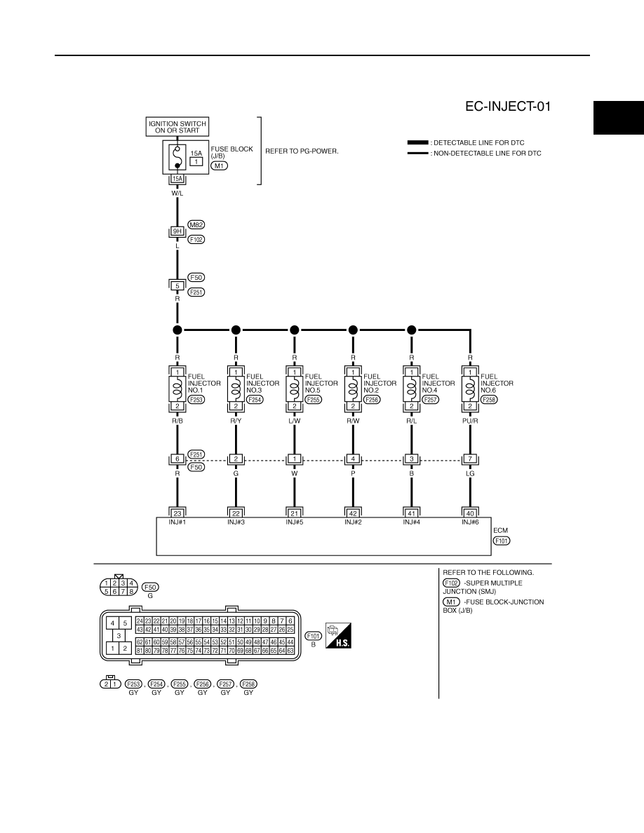
Wiring Diagram
INFOID:0000000001326440
Specification data are reference values and are measured between each terminal and ground.
Pulse signal is measured by CONSULT-III.
CAUTION:
TBWM1408E
EC-554
< SERVICE INFORMATION >
[VQ35DE]
FUEL INJECTOR
Do not use ECM ground terminals when measuring input/output voltage. Doing so may result in dam-
age to the ECM's transistor. Use a ground other than ECM terminals, such as the ground.
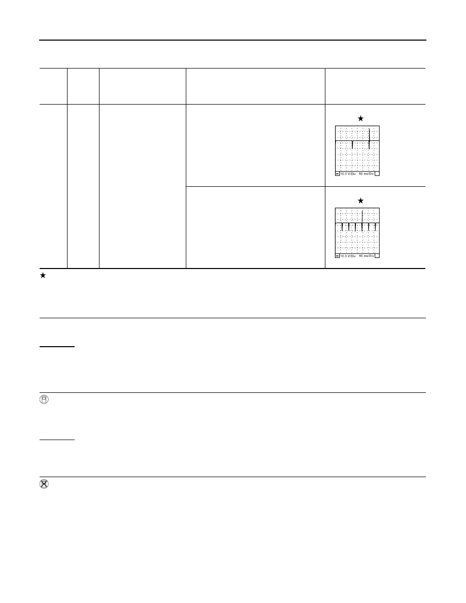
: Average voltage for pulse signal (Actual pulse signal can be confirmed by oscilloscope.)
Diagnosis Procedure
INFOID:0000000001326441
1.
INSPECTION START
Turn ignition switch to START.
Is any cylinder ignited?
Yes or No
Yes (With CONSULT-III)>>GO TO 2.
Yes (without CONSULT-III)>>GO TO 3.
No
>> GO TO 6.
2.
CHECK OVERALL FUNCTION
With CONSULT-III
1.
Start engine.
2.
Perform “POWER BALANCE” in “ACTIVE TEST” mode with CONSULT-III.
3.
Make sure that each circuit produces a momentary engine speed drop.
OK or NG
OK
>> INSPECTION END
NG
>> GO TO 6.
3.
CHECK FUNCTION OF FUEL INJECTOR-I
Without CONSULT-III
1.
Turn ignition switch OFF.
TER-
MI-
NAL
NO.
WIRE
COLOR
ITEM
CONDITION
DATA (DC Voltage)
21
22
23
40
41
42
W
G
R
LG
B
P
Fuel injector No. 5
Fuel injector No. 3
Fuel injector No. 1
Fuel injector No. 6
Fuel injector No. 4
Fuel injector No. 2
[Engine is running]
• Warm-up condition
• Idle speed
NOTE:
The pulse cycle changes depending on rpm
at idle
BATTERY VOLTAGE
(11 - 14V)
[Engine is running]
• Warm-up condition
• Engine speed: 2,000 rpm
BATTERY VOLTAGE
(11 - 14V)
SEC984C
SEC985C
FUEL INJECTOR
EC-555
< SERVICE INFORMATION >
[VQ35DE]
C
D
E
F
G
H
I
J
K
L
M
A
EC
N
P
O
2.
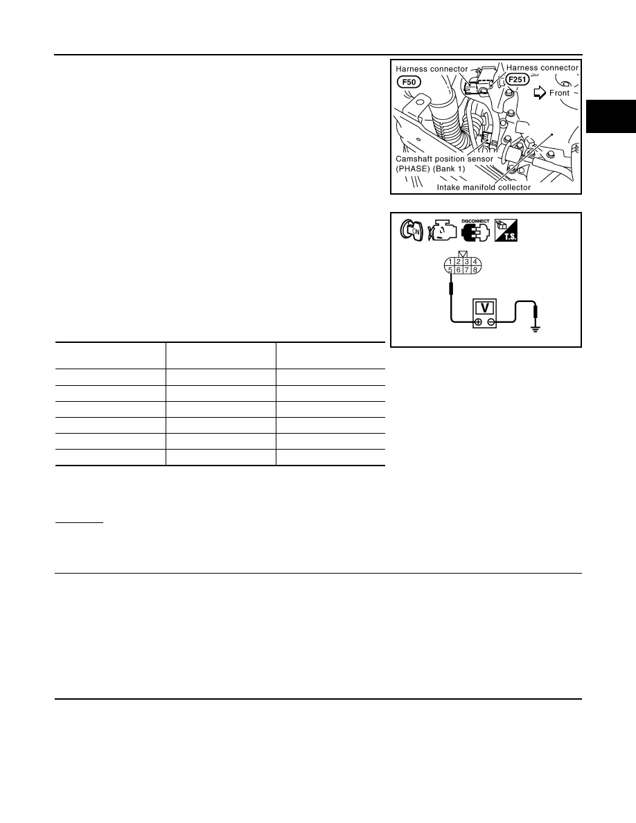
Disconnect harness connector F50, F251
3.
Turn ignition switch ON.
4.
Check voltage between harness connector F50 terminal 5 and
ground.
5.
Turn ignition switch OFF.
6.
Disconnect ECM harness connector.
7.
Check harness continuity between harness connector F50 and
ECM as follows.
Refer to Wiring Diagram.
8.
Also check harness for short to ground and short to power.
OK or NG
OK
>> GO TO 5.
NG
>> GO TO 4.
4.
DETECT MALFUNCTIONING PART
Check the following.
• Harness connectors M82, F102
• Fuse block (J/B) connector M1
• 15A fuse
• Harness for open or short between harness connector F50 and fuse
• Harness for open or short between harness connector F50 and ECM
>> Repair open circuit or short to ground or short to power in harness or connectors.
5.
CHECK FUNCTION OF FUEL INJECTOR-II
PBIB2624E
Voltage: Battery voltage
Cylinder
Harness connector F50
terminal
ECM terminal
1
6
23
2
4
42
3
2
22
4
3
41
5
1
21
6
7
40
Continuity should exist.
PBIB2323E
EC-556
< SERVICE INFORMATION >
[VQ35DE]
FUEL INJECTOR
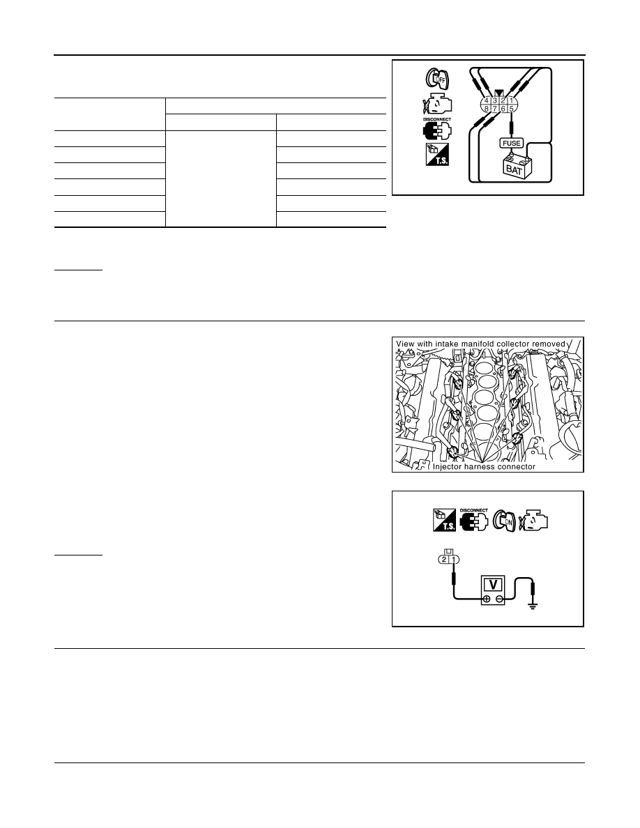
Provide battery voltage between harness connector F251 as follows
and then interrupt it. Listen to each fuel injector operating sound.
OK or NG
OK
>> INSPECTION END
NG
>> GO TO 6.
6.
CHECK FUEL INJECTOR POWER SUPPLY CIRCUIT
1.
Turn ignition switch OFF.
2.
Disconnect fuel injector harness connector.
3.
Turn ignition switch ON.
4.
Check voltage between fuel injector terminal 1 and ground with
CONSULT-III or tester.
OK or NG
OK
>> GO TO 8.
NG
>> GO TO 7.
7.
DETECT MALFUNCTIONING PART
Check the following.
• Harness connectors M82, F102
• Fuse block (J/B) connector M1
• 10A fuse
• Harness for open or short between fuel injector and fuse
>> Repair open circuit or short to ground or short to power in harness or connectors.
8.
CHECK FUEL INJECTOR OUTPUT SIGNAL CIRCUIT FOR OPEN AND SHORT
1.
Turn ignition switch OFF.
2.
Disconnect ECM harness connector.
Cylinder
Harness connector F251 terminal
(+)
(–)
1
5
6
2
4
3
2
4
3
5
1
6
7
Operating sound should exist.
PBIB2497E
PBIB1561E
Voltage: Battery voltage
PBIB0582E
Нет комментариевНе стесняйтесь поделиться с нами вашим ценным мнением.
Текст