Infiniti M35/M45 Y50. Manual — part 768

FRONT FINAL DRIVE ASSEMBLY
FFD-19
C
E
F
G
H
I
J
K
L
M
A
B
FFD
●
If the tooth contact is near the face (face contact), or near the
heel (heel contact), thicken pinion height adjusting washers to
move drive pinion closer to drive gear.
Refer to
FFD-36, "Pinion Height Adjusting Washer"
.
●
If the tooth contact is near the flank (flank contact), or near the
toe (toe contact), thin pinion height adjusting washers to move
drive pinion farther from drive gear.
Refer to
FFD-36, "Pinion Height Adjusting Washer"
.
Backlash
1.
Remove carrier cover. Refer to
FFD-20, "Differential Assembly"
2.
Fit a dial indicator to the drive gear face to measure the back-
lash.
●
If the backlash is outside of the specified value, change the
thickness of side bearing adjusting washer.
Companion Flange Runout
1.
Fit a dial indicator onto the companion flange face (inner side of
the propeller shaft mounting bolt holes).
2.
Rotate companion flange to check for runout.
3.
Fit a test indicator to the inner side of companion flange (socket
diameter).
4.
Rotate companion flange to check for runout.
5.
If the runout value is outside the runout limit, follow the proce-
dure below to adjust.
a.
Check for runout while changing the phase between companion flange and drive pinion by 90
°
step, and
search for the position where the runout is the minimum.
b.
If the runout value is still outside of the limit after the phase has been changed, possible cause will be an
assembly malfunction of drive pinion and pinion bearing and malfunction of pinion bearing. Check for
these items and repair if necessary.
PDIA0440E
PDIA0441E
Backlash:
0.10 - 0.15 mm (0.0039 - 0.0059 in)
When the backlash is large:
Decrease side bearing adjusting washer thickness.
Refer to
FFD-36, "Side Bearing Adjusting Washer"
.
When the backlash is small:
Increase side bearing adjusting washer thickness.
Refer to
FFD-36, "Side Bearing Adjusting Washer"
.
SDIA0009J
Runout limit:
0.18 mm (0.0070 in)
Runout limit:
0.13 mm (0.0051 in)
PDIA0646E
FFD-20
FRONT FINAL DRIVE ASSEMBLY
c.
If the runout value is still outside of the limit after the check and repair, replace companion flange.
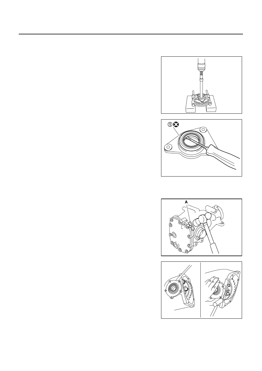
DISASSEMBLY
Side Shaft Assembly
1.
Hold extension tube retainer with puller, then press out side
shaft using a press.
2.
Remove side shaft oil seal (1) from extension tube retainer with
a flat- blade screwdriver.
CAUTION:
Be careful not to damage extension tube retainer.
3.
Remove side shaft bearing from extension tube retainer.
4.
Remove O-ring from extension tube retainer.
5.
Remove dust sealed from side shaft.
Differential Assembly
1.
Drain gear oil, if necessary.
2.
Remove carrier cover mounting bolts.
3.
Remove carrier cover to insert the seal cutter between gear car-
rier and carrier cover.
CAUTION:
●
Be careful not to damage the mating surface.
●
Do not insert flat-bladed screwdriver, this way damage
the mating surface.
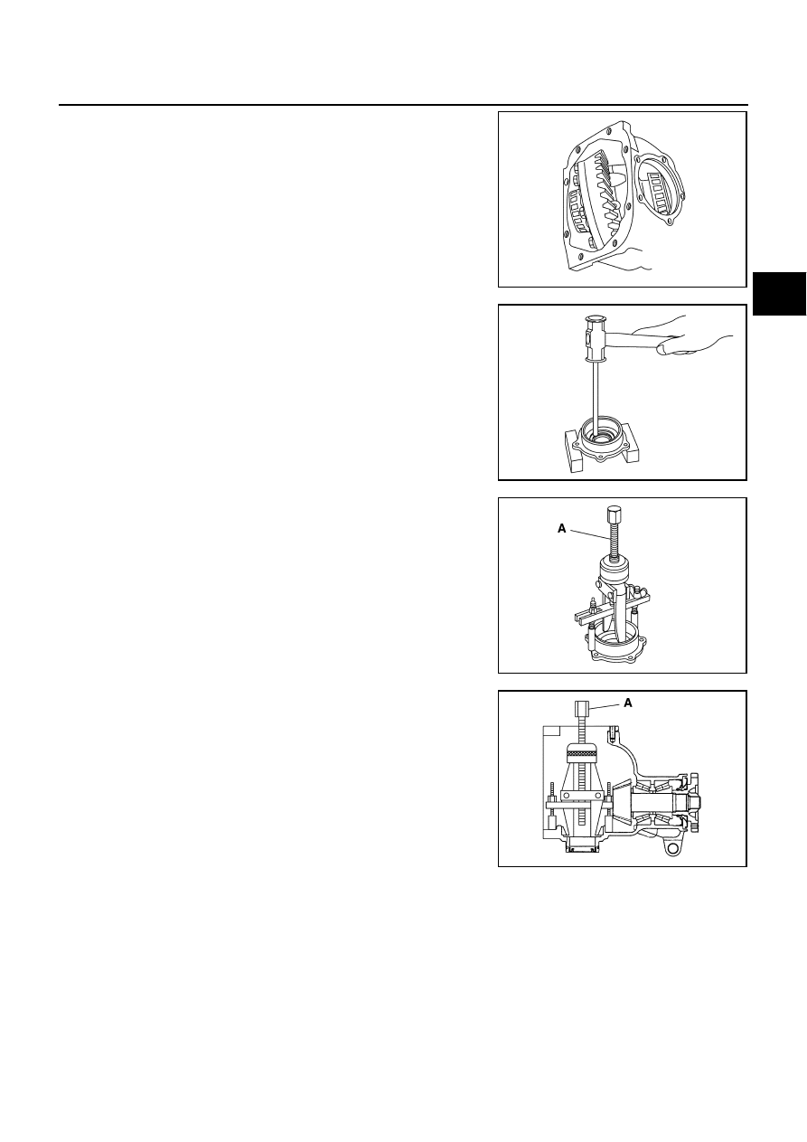
4.
Remove side retainer.
5.
Remove side bearing adjusting shim.
6.
Remove O-ring from side retainer.
PDIA0793J
PDIA0794J
Tool number
A: KV10111100 (J-37228)
PDIA0795J
PDIA0670E
FRONT FINAL DRIVE ASSEMBLY
FFD-21
C
E
F
G
H
I
J
K
L
M
A
B
FFD
7.
Remove differential case assembly from gear carrier.
8.
Remove side oil seal (right side) from side retainer.
9.
Remove side bearing outer race with puller.
10. Remove O-ring from gear carrier.
11. Remove side oil seal (left side) from gear carrier.
12. Remove side bearing outer race with puller.
PDIA0671E
PDIA0672E
Tool number
A: KV381054S0 (J-34286)
PDIA0796J
Tool number
A: KV381054S0 (J-34286)
PDIA0797J
FFD-22
FRONT FINAL DRIVE ASSEMBLY
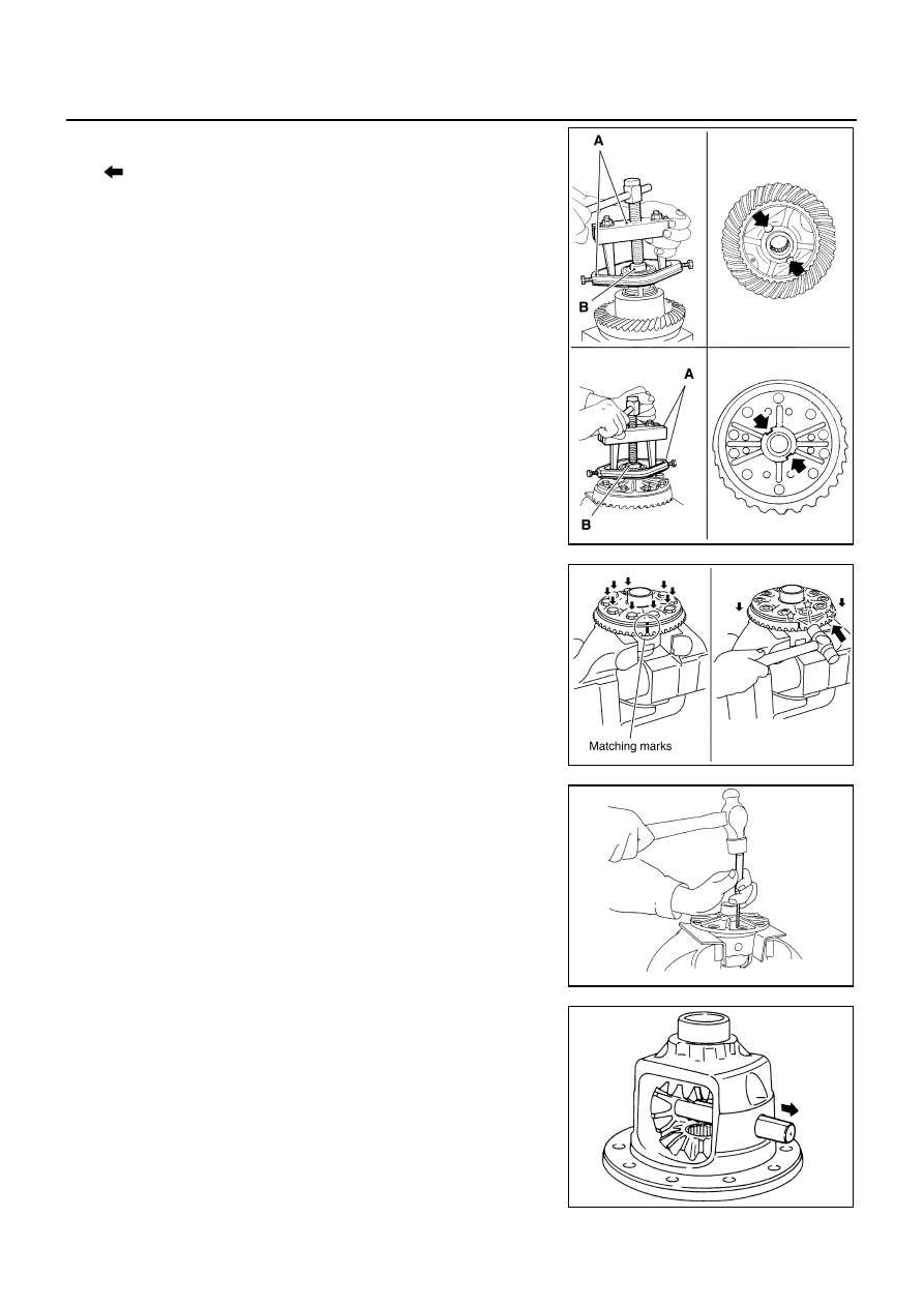
13. Remove side bearing inner race.
To prevent damage to bearing, engage puller jaws in groove
(
).
CAUTION:
●
To prevent damage to the side bearing and drive gear,
place copper plates between these parts and vise.
●
It is not necessary to remove side bearing inner race
except it is replaced.
14. For proper reinstallation, paint matching marks on one differen-
tial case assembly.
CAUTION:
For matching marks, use paint. Do not damage differential
case and drive gear.
15. Remove drive gear mounting bolts.
16. Tap drive gear off differential case assembly with a soft hammer.
CAUTION:
Tap evenly all around to keep drive gear from bending.
17. Remove lock pin of pinion mate shaft with a punch from drive
gear side.
18. Remove pinion mate shaft.
Tool number
A: ST33051001 (J-22888-20)
B: ST33061000 (J-8107-2)
PDIA0758J
PDIA0496E
PDIA0759J
SDIA0031J
Нет комментариевНе стесняйтесь поделиться с нами вашим ценным мнением.
Текст