Infiniti M35/M45 Y50. Manual — part 252

INTELLIGENT KEY SYSTEM
BL-77
C
D
E
F
G
H
J
K
L
M
A
B
BL
Trouble Diagnosis Procedure
NIS001XG
WORK FLOW
1.
CHECK IN
CHECK IN.
>> GO TO 2.
2.
GET SYMPTOMS
Listen to customer complaints request. (Get symptoms)
NOTE:
If customer reports a “No start” condition, request all Intelligent Keys to be brought to the dealer in case of
Intelligent Key system malfunction.
Intelligent Key service request>>Refer to CONSULT-II operation manual.
Intelligent Key system is malfunctioning>>GO TO 3.
3.
PERFORM SELF-DIAGNOSIS
Perform self-diagnosis of Intelligent Key system with CONSULT-II.
“SELF-DIAG RESULTS” are displayed>>GO TO
BL-79, "SELF-DIAGNOSTIC RESULTS"
.
“SELF-DIAG RESULTS” are not displayed>>GO TO 4.
4.
CHECK FUNCTION OF INTELLIGENT KEY SYSTEM
Does all function of Intelligent Key system operate?
All function of Intelligent Key system does not operate>>GO TO
BL-84, "ALL FUNCTIONS OF INTELLI-
GENT KEY SYSTEM DOES NOT OPERATE"
Specific function of Intelligent Key system does not operate>>GO TO 5.
5.
CHECK POWER DOOR LOCK OPERATION
Does door lock/unlock operation by door lock and unlock switch operate?
OK or NG
OK
>> GO TO 6.
NG
>> Refer to
BL-24, "POWER DOOR LOCK SYSTEM"
.
6.
CHECK DOOR REQUEST SWITCH OPERATION
Does door lock/unlock operation by door request switch operate?
OK or NG
OK
>> GO TO 7.
NG
BL-84, "DOOR LOCK/UNLOCK FUNCTION MALFUNCTION"
.
7.
CHECK TRUNK OPEN OPERATION
Does the trunk open operation by the trunk opener switch operate?
OK or NG
OK
>> GO TO 8.
NG
>> Refer to

BL-78
INTELLIGENT KEY SYSTEM
8.
CHECK TRUNK OPENER REQUEST SWITCH OPERATION
Does the trunk open operation by the trunk opener request switch operate?
OK or NG
OK
>> GO TO 9.
NG
>> GO TO
BL-86, "TRUNK OPEN FUNCTION MALFUNCTION"
.
9.
CHECK REMOTE KEYLESS FUNCTION
Does the following operation by the Intelligent Key remote control button operate?
●
Door lock/unlock function
●
Trunk open function
●
Panic alarm function
OK or NG
OK
>> GO TO 10.
NG
>> GO TO
BL-85, "REMOTE KEYLESS ENTRY FUNCTION MALFUNCTION"
10.
CHECK POWER WINDOW OPERATION
Does power window operation by power window main switch operate?
OK or NG
OK
>> GO TO 11.
NG
>> Refer to
11.
CHECK POWER WINDOW DOWN FUNCTION
Does power window down function by Intelligent Key remote control button operate?
OK or NG
OK
>> GO TO 12.
NG
>> GO TO
BL-88, "POWER WINDOW DOWN FUNCTION MALFUNCTION"
12.
CHECK HAZARD AND BUZZER REMINDER FUNCTION BY REQUEST SWITCH
Does hazard and buzzer reminder function by the following switches operate?
●
Door request switches
●
Trunk opener request switch
OK or NG
OK
>> GO TO 13.
NG
>> GO TO
BL-87, "HAZARD AND BUZZER REMINDER FUNCTION MALFUNCTION"
13.
CHECK HAZARD AND HORN REMINDER FUNCTION BY INTELLIGENT KEY BUTTON
Does hazard and horn reminder function by Intelligent Key button operate?
OK or NG
OK
>> GO TO 14.
NG
>> GO TO
BL-87, "HAZARD AND HORN REMINDER FUNCTION MALFUNCTION"
.
14.
CHECK WARNING FUNCTION
Does warning function operate? Refer to
OK or NG
OK
>> GO TO 15.
NG
>> Refer to
INTELLIGENT KEY SYSTEM
BL-79
C
D
E
F
G
H
J
K
L
M
A
B
BL
15.
CHECK OUT
CHECK OUT.
>> INSPECTION END
CONSULT-II Functions (INTELLIGENT KEY)
NIS001XH
CONSULT-II can display each diagnostic item using the diagnostic test modes as shown below.
CONSULT-II Inspection Procedure
NIS001XI
CAUTION:
If CONSULT-II is used with no connection CONSULT-II CONVERTER, malfunctions might be detected
in self-diagnosis depending on control unit which performs CAN Communication.
BASIC OPERATION
Refer to
GI-38, "CONSULT-II Start Procedure"
.
CONSULT-II Application Items
NIS001XJ
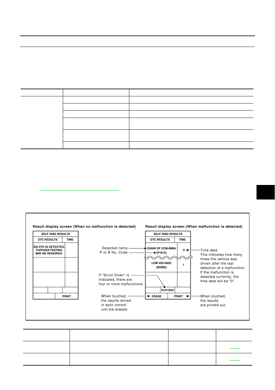
SELF-DIAGNOSTIC RESULTS
How to Read SELF-DIAGNOSTIC RESULTS
Part to be diagnosed
Test item, Diagnosis mode
Description
Intelligent Key
WORK SUPPORT
Changes settings for each function.
SELF-DIAG RESULTS
Intelligent Key unit performs CAN communication diagnosis.
DATA MONITOR
Displays Intelligent Key unit input data in real time.
CAN DIAGNOSTIC SUPPORT
MONITOR
The results of transmit/receive diagnosis of CAN Communication can
be read.
ACTIVE TEST
Operation of electrical loads can be checked by sending driving signal
to then.
ECU PART NUMBER
Displays Intelligent Key unit part No.
PIIB6280E
Suspect Systems
[DTC]
Diagnostic item is detected when...
Repair work
Reference page
CAN COMM CIRCUIT
[U1000]
Malfunction is detected in CAN communication
Perform CAN communi-
cation system inspection
CONTROL UNIT (CAN)
[U1010]
Malfunction is detected in CAN communication caused
by Intelligent Key unit internal malfunction
Replace Intelligent Key
unit.

BL-80
INTELLIGENT KEY SYSTEM
CAUTION:
When CAN COMM [U1000] and CONTROL UNIT (CAN) [U1010] are displayed, give priority to performing trouble diagnosis.
DATA MONITOR
STRG COMM 1
[B2013]
Communication malfunction with steering lock unit is
detected
Check steering lock unit
STEERING LOCK UNIT
[B2551]
Even if the communication with steering lock unit is
normally performed, the steering lock is malfunctioning
Replace steering lock
unit
INTELLIGENT KEY
[B2552]
Internal malfunction is detected in Intelligent Key unit
Replace Intelligent Key
unit.
IGN POWER CIRCUIT
[B2553]
It continues for 2 seconds or more that ON power sup-
ply input to Intelligent Key unit is excessively low when
the power supply position is in ON position
Check Intelligent Key
unit ON power supply
input
ACC POWER CIRCUIT
[B2554]
It continues for 2 seconds or more that ACC power
supply input to Intelligent Key unit is excessively low
when the power supply position is in ACC or ON posi-
tion
Check Intelligent Key
unit ACC power supply
input
STOP LAMP CIRCUIT
[B2555]
5V or less is detected at both the stop lamp switch sig-
nal input circuit that is input to Intelligent Key unit and
the monitor input before stop lamp switch
Check stop lamp switch
ENG START SW
[B2556]
Condition that push-button ignition switch is pushed is
detected continuously for 100 seconds or more
Check push-button igni-
tion switch
VEHICLE SPEED
[B2557]
Some differences occur on one or more vehicle speed
inputs of Intelligent Key unit
Check vehicle speed sig-
nal
SHIFT POSITION
[B2558]
●
There is a difference between the shift position input
via CAN communication and the P position input by
detente switch
●
Vehicle speed (5 km/h or more) is detected continu-
ously for 10 seconds or more even if the shift posi-
tion is detected in P position when the power supply
position is in ON position
Check shift position input
PDU
[B2559]
Internal malfunction is detected in PDU
Replace PDU
START POW SUP CIRC
[B2560]
Though the engine start operation is not performed,
starter relay in IPDM E/R is ON
Check starter power sup-
ply
LOW VOLTAGE
[B2562]
Battery power supply input to Intelligent Key unit (8.8V
or less) is detected continuously for 1.5 seconds or
more
Check battery low volt-
age
HI VOLTAGE
[B2563]
Battery power supply input to Intelligent Key unit (18V
or more) is detected continuously for 90 seconds or
more
Check for battery high
voltage
NATS MALFUNCTION
[B2590]
Malfunction is detected in immobilizer system
Check (IVIS) NATS trou-
ble diagnosis procedure
Suspect Systems
[DTC]
Diagnostic item is detected when...
Repair work
Reference page
Monitor item
Content
DR REQ SW
Indicates [ON/OFF] condition of door request switch (driver side).
AS REQ SW
Indicates [ON/OFF] condition of door request switch (passenger side).
BD/TR REQ SW
Indicates [ON/OFF] condition of trunk opener request switch.
ON POS
Indicates [ON/OFF] condition of ignition switch in ON position.
ACC POS
Indicates [ON/OFF] condition of ignition switch in ACC position.
DOOR STAT SW
Indicates [ON/OFF] condition of door unlock sensor.
STOP LAMP SW
Indicates [ON/OFF] condition of stop lamp switch.
P RANGE SW
Indicates [ON/OFF] condition of park position switch.
Нет комментариевНе стесняйтесь поделиться с нами вашим ценным мнением.
Текст