Infiniti M35/M45 Y50. Manual — part 937
ILLUMINATION
LT-293
C
D
E
F
G
H
I
J
L
M
A
B
LT
ILLUMINATION
PFP:27545
System Description
NKS003TH
Control of the illumination lamps operation is dependent upon the position of the lighting switch (combination
switch). When the lighting switch is placed in the 1ST or 2ND position (or if the auto light system is activated)
the BCM (body control module) receives input signal requesting the illumination lamps to illuminate. This input
signal is communicated to the IPDM E/R (intelligent power distribution module engine room) across the CAN
communication lines. The CPU (central processing unit) located in the IPDM E/R controls the tail lamp relay
coil. This relay, when energized, directs power to the illumination lamps, which then illuminate.
OUTLINE
Power is supplied at all times
●
through 15A fuse (No. 71, located in IPDM E/R)
●
to tail lamp relay, located in IPDM E/R, and
●
to CPU located in IPDM E/R,
●
through 15A fuse (No. 78, located in IPDM E/R)
●
to CPU located in IPDM E/R,
●
through 50A fusible link (letter F, located in fuse, fusible link and relay block)
●
to BCM terminal 55,
●
through 10A fuse [No. 21, located in fuse block (J/B)]
●
to BCM terminal 42 and
●
to combination meter terminal 23,
●
through 10A fuse [No. 19, located in fuse block (J/B)]
●
to unified meter and A/C amp. terminal 54,
●
through 10A fuse [No. 22, located in fuse block (J/B)]
●
to intelligent key unit terminals 1, 41 and 57.
With the ignition switch in the ON or START position, power is supplied
●
through 15A fuse [No. 1, located in fuse block (J/B)]
●
to BCM terminal 38,
●
through 10A fuse [No. 14, located in fuse block (J/B)]
●
to combination meter terminal 12,
●
through 10A fuse [No. 12, located in fuse block (J/B)]
●
to unified meter and A/C amp. terminal 53 and
●
to rear sunshade cancel relay terminal 1.
With the ignition switch in the ACC or ON position, power is supplied
●
through 10A fuse [No. 6, located in fuse block (J/B)]
●
to BCM terminal 11
●
to unified meter and A/C amp. terminal 41 and
●
to combination meter terminal 2.
Ground is supplied
●
to BCM terminal 52
●
to unified meter and A/C amp. terminals 55 and 71
●
to combination meter terminals 9, 10, and 11
●
to Intelligent Key unit terminals 20, 40, 56 and 72, and
●
to illumination control switch terminal 3
●
through grounds M16 and M70,
●
to IPDM E/R terminals 38 and 51
●
through grounds E22 and E43.
LT-294
ILLUMINATION
ILLUMINATION OPERATION BY LIGHTING SWITCH
With the lighting switch in the 1ST or 2ND position (or if the auto light system is activated), the BCM receives
input signal requesting the illumination lamps to illuminate. This input signal is communicated to the IPDM E/R
across the CAN communication lines. The CPU located in the IPDM E/R controls the tail lamp relay coil,
which, when energized, directs power
●
through IPDM E/R terminal 21
●
to combination meter terminal 13
●
to LDW switch (illumination) terminal 5 (with lane departure warning)
●
to VDC off switch (illumination) terminal 3
●
to trunk lid opener switch (illumination) terminal 3
●
to combination switch (spiral cable) terminal 24
●
to door mirror remote control switch (illumination) terminal 16
●
to AFS switch (illumination) terminal 5 (with AFS)
●
to rear sunshade front switch (illumination) terminal 5 (with rear control switch)
●
to A/T illumination terminal 1
●
to snow mode switch (illumination) terminal 5 (AWD models)
●
to rear control cancel switch (illumination) terminal 4 (with rear control switch)
●
to clock terminal 3
●
to multifunction switch terminal 3
●
to audio unit terminal 9
●
to DVD player terminal 18 (with DVD player)
●
to NAVI control unit terminal 61 (with navigation system)
●
to AV control unit terminal 61 (without navigation system)
●
to climate controlled seat switch driver side (illumination) terminal 7 (with climate controlled seat)
●
to climate controlled seat switch passenger side (illumination) terminal 7 (with climate controlled seat)
●
to ashtray illumination (rear LH) terminal 1
●
to ashtray illumination (rear RH) terminal 1
●
to illumination control switch terminal 1
●
to cigarette lighter socket (illumination) terminal 2
●
to map lamp (illumination) terminal 8
●
to power window main switch illumination terminal 1
●
to glove box lamp terminal 1
●
to rear control switch terminal 2
●
to rear power seat switch RH (illumination) terminal 4 (with rear control switch)
●
to rear heated seat switch RH (illumination) terminal 7 (with rear control switch)
●
to rear sunshade cancel relay terminal 6 (with rear control switch)
●
to automatic return cancel switch (illumination) terminal 4 (with rear control switch)
●
to rear power seat switch LH (illumination) terminal 4 (with rear control switch) and
●
to rear heated seat switch LH (illumination) terminal 7 (with rear control switch),
●
through Intelligent Key unit terminal 12
●
to push button ignition switch (illumination) terminal 3.
Ground is supplied
●
to combination meter terminal 14
●
to combination meter terminal 9, 10 and 11
●
to push button ignition switch (illumination) terminal 2
●
to LDW switch (illumination) terminal 4 (with lane departure warning)
●
to VDC off switch (illumination) terminal 4
●
to trunk lid opener switch (illumination) terminal 4
●
to combination switch (spiral cable) terminal 25
ILLUMINATION
LT-295
C
D
E
F
G
H
I
J
L
M
A
B
LT
●
to door mirror remote control switch (illumination) terminal 15
●
to AFS switch (illumination) terminal 6 (with AFS)
●
to rear sunshade front switch (illumination) terminal 6 (with rear control switch)
●
to A/T illumination terminal 2
●
to snow mode switch (illumination) terminal 6 (ADW models)
●
to rear control cancel switch (illumination) terminal 5 (with rear control switch)
●
to clock terminal 4
●
to multifunction switch terminal 4
●
to audio unit terminal 8
●
to DVD player terminal 17 (With DVD player)
●
to climate controlled seat switch driver side (illumination) terminal 8 (with climate controlled seat) and
●
to climate controlled seat switch passenger side (illumination) terminal 8 (with climate controlled seat)
●
through illumination control switch terminal 2
●
to illumination control switch terminal 3
●
through grounds M16 and M70,
●
to cigarette lighter socket (illumination) terminal 1
●
to map lamp (illumination) terminal 4
●
to power window main switch illumination terminal 2 and
●
to glove box lamp terminal 2
●
through grounds M16 and M70,
●
to ashtray illumination (rear RH) terminal 2
●
through grounds B402, B405,
●
to ashtray illumination (rear LH) terminal 2
●
to automatic return cancel switch (illumination) terminal 2 (With rear control switch)
●
to rear power seat switch LH (illumination) terminal 3 (With rear control switch)
●
to rear heated seat switch LH (illumination) terminal 8 (With rear control switch)
●
through grounds B5, B40 and B131,
●
through rear sunshade cancel relay terminal 7(With rear control switch)
●
to rear sunshade rear switch (illumination) terminal 7 (With rear control switch)
●
through grounds B5, B40, B131 and B559.
●
to rear control switch terminal 4
●
to rear power seat switch RH (illumination) terminal 3 (With rear control switch)
●
to rear heated seat switch RH (illumination) terminal 8 (With rear control switch)
●
through grounds B5, B40, B131 and B559.
With power and ground supplied, illumination lamps illuminate.
EXTERIOR LAMP BATTERY SAVER CONTROL
BCM activates the exterior lamp battery saver control function and turns off the exterior lamps to prevent bat-
tery from over discharge when the combination switch (lighting switch) is in 1ST or 2ND position and/or the
front fog lamp switch ON and the door lock operation is performed by keyless entry system.
CAN Communication System Description
NKS003TI
CAN (Controller Area Network) is a serial communication line for real time application. It is an on-vehicle mul-
tiplex communication line with high data communication speed and excellent error detection ability. Many elec-
tronic control units are equipped onto a vehicle, and each control unit shares information and links with other
control units during operation (not independent). In CAN communication, control units are connected with 2
communication lines (CAN H line, CAN L line) allowing a high rate of information transmission with less wiring.
Each control unit transmits/receives data but selectively reads required data only.
CAN Communication Unit
NKS003TJ
Refer to
LAN-50, "CAN System Specification Chart"
.
LT-296
ILLUMINATION
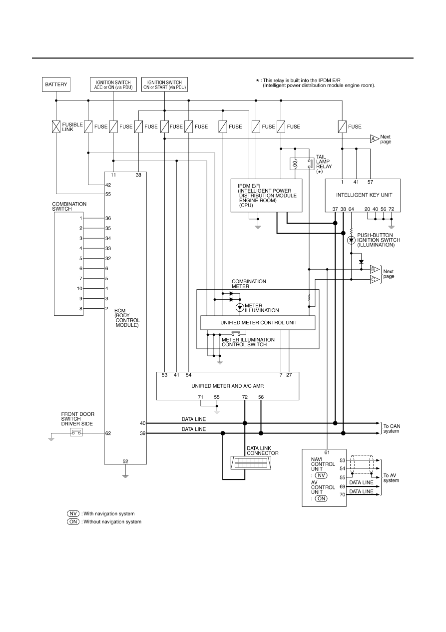
Schematic
NKS003TK
TKWT5071E
Нет комментариевНе стесняйтесь поделиться с нами вашим ценным мнением.
Текст