Infiniti M35/M45 Y50. Manual — part 987
HARNESS
PG-93
C
D
E
F
G
H
I
J
L
M
A
B
PG
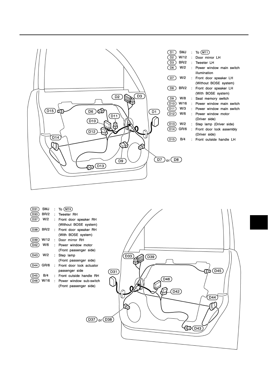
FRONT DOOR HARNESS
LH Side
RH Side
TKIT0468E
TKIT0469E
PG-94
HARNESS
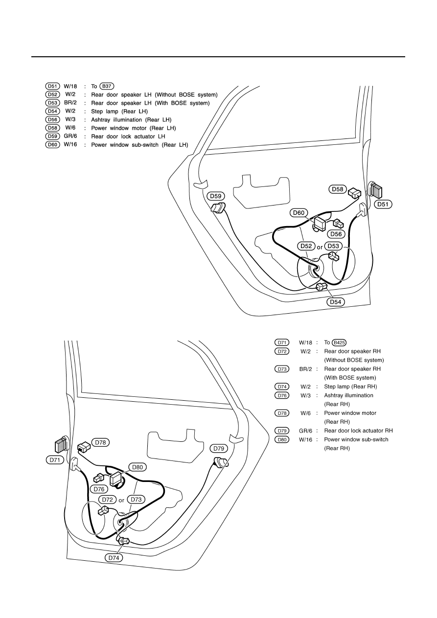
REAR DOOR HARNESS
LH Side
RH Side
TKIT0470E
TKIT0772E

HARNESS
PG-95
C
D
E
F
G
H
I
J
L
M
A
B
PG
Wiring Diagram Codes (Cell Codes)
NKS004ET
Use the chart below to find out what each wiring diagram code stands for.
Refer to the wiring diagram code in the alphabetical index to find the location (page number) of each wiring
diagram.
Code
Section
Wiring Diagram Name
A/C
ATC
Air Conditioner
AF1B1
EC
Air Fuel Ratio Sensor 1 Bank 1
AF1B2
EC
Air Fuel Ratio Sensor 1 Bank 2
AF1HB1
EC
Air Fuel Ratio Sensor 1 Heater Bank 1
AF1HB2
EC
Air Fuel Ratio Sensor 1 Heater Bank 2
AFS
LT
Adaptive Front Lighting System
APPS1
EC
Accelerator Pedal Position Sensor
APPS2
EC
Accelerator Pedal Position Sensor
APPS3
EC
Accelerator Pedal Position Sensor
ASC/BS
EC
Automatic Speed Control Device (ASCD) Brake Switch
ASC/SW
EC
Automatic Speed Control Device (ASCD) Steering Switch
ASCBOF
EC
Automatic Speed Control Device (ASCD) Brake Switch
ASCIND
EC
Automatic Speed Control Device (ASCD) Indicator
AT/IND
DI
A/T Indicator Lamp
AUT/DP
SE
Automatic Drive Positioner
AUTO/L
LT
Automatic Light System
AV
AV
Audio and Visual System
AWD
TF
AWD Control System
BACK/L
LT
Back-Up Lamp
BRK/SW
EC
Brake Switch
C/SEAT
SE
Climate Controlled Seat
CAN
AT
CAN Communication Line
CAN
EC
CAN Communication Line
CAN
LAN
CAN System
CHARGE
SC
Charging System
CHIME
DI
Warning Chime
CIGAR
WW
Cigarette Lighter
CLOCK
DI
Clock
COMBSW
LT
Combination Switch
COMPAS
DI
Compass and Thermometer
COOL/F
EC
Cooling Fan Control
CUR/SE
EC
Battery Current Sensor
D/LOCK
BL
Power Door Lock
DEF
GW
Rear Window Defogger
DTRL
LT
Headlamp - with Daytime Light System
ECM/PW
EC
ECM Power Supply for Back-Up
ECTS
EC
Engine Coolant Temperature Sensor
ENG/ST
BL
Engine Start System
EPS
STC
Electric Controlled Power Steering System
ETC1
EC
Electric Throttle Control Function
ETC2
EC
Electric Throttle Control Motor Relay

PG-96
HARNESS
ETC3
EC
Electric Throttle Control Motor
F/FOG
LT
Front Fog Lamp
F/PUMP
EC
Fuel Pump
FPCM
EC
Fuel Pump Control Module
FTS
AT
A/T Fluid Temperature Sensor Circuit
FTTS
EC
Fuel Tank Temperature Sensor
FUELB1
EC
Fuel Injection System Function (Bank 1)
FUELB2
EC
Fuel Injection System Function (Bank 2)
H/LAMP
LT
Headlamp
HORN
WW
Horn
HSEAT
SE
Heated Seat
I/KEY
BL
Intelligent Key System
I/MIRR
GW
Inside Mirror (Auto Anti-Dazzling Mirror)
IATS
EC
Intake Air Temperature Sensor
ICC
ACS
Intelligent Cruise Control System
ICC/BS
EC
ICC Brake Switch
ICC/SW
EC
ICC Steering Switch
ICCBOF
EC
ICC Brake Switch
IGNSYS
EC
Ignition System
ILL
LT
Illumination
INJECT
EC
Injector
IVCB1
EC
Intake Valve Timing Control Solenoid Valve Bank 1
IVCB2
EC
Intake Valve Timing Control Solenoid Valve Bank 2
IVCSB1
EC
Intake Valve Timing Control Position Sensor Bank 1
IVCSB2
EC
Intake Valve Timing Control Position Sensor Bank 2
IVTB1
EC
Intake Valve Timing Control System (Bank 1)
IVTB2
EC
Intake Valve Timing Control System (Bank 2)
KS
EC
Knock Sensor
LDW
DI
Lane Departure Warning System
MAFS
EC
Mass Air Flow Sensor
MAIN
AT
Main Power Supply and Ground Circuit
MAIN
EC
Main Power Supply and Ground Circuit
METER
DI
Speedometer, Tachometer, Temp., Oil and Fuel Gauges
MIL/DL
EC
MIL & Data Link Connector
MIRROR
GW
Door Mirror
MMSW
AT
Manual Mode Switch
NATS
BL
Nissan Anti-Theft System
NONDTC
AT
Non-Detective Items
O2H2B1
EC
Heated Oxygen Sensor 2 Heater Bank 1
O2H2B2
EC
Heated Oxygen Sensor 2 Heater Bank 2
O2S2B1
EC
Heated Oxygen Sensor 2 Bank 1
O2S2B2
EC
Heated Oxygen Sensor 2 Bank 2
P/SCKT
WW
Power Socket
PDU
PG
Power Distribution Unit
Code
Section
Wiring Diagram Name
Нет комментариевНе стесняйтесь поделиться с нами вашим ценным мнением.
Текст