Infiniti M35/M45 Y50. Manual — part 411
TROUBLE DIAGNOSIS
EC-117
[VQ35DE]
C
D
E
F
G
H
I
J
K
L
M
A
EC
21
22
23
40
41
42
W
R/Y
R/B
V/R
P/L
R/W
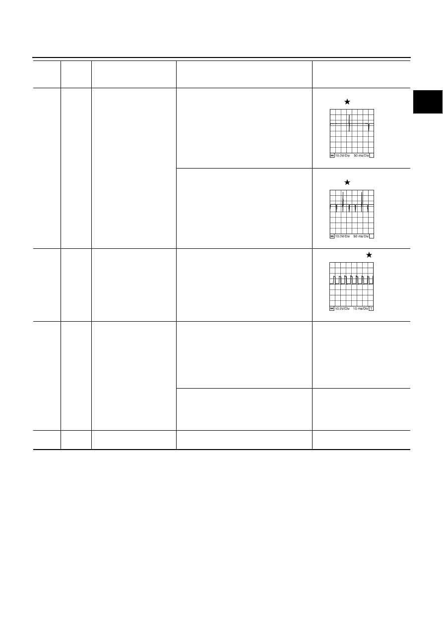
Fuel injector No. 5
Fuel injector No. 3
Fuel injector No. 1
Fuel injector No. 6
Fuel injector No. 4
Fuel injector No. 2
[Engine is running]
●
Warm-up condition
●
Idle speed
NOTE:
The pulse cycle changes depending on rpm
at idle
BATTERY VOLTAGE
(11 - 14V)
[Engine is running]
●
Warm-up condition
●
Engine speed: 2,000 rpm
BATTERY VOLTAGE
(11 - 14V)
24
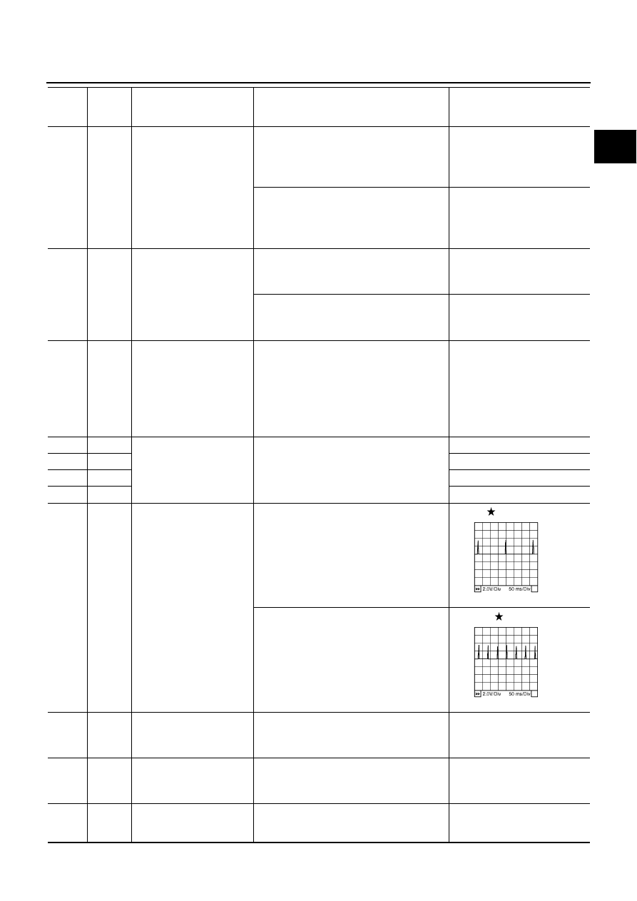
O
A/F sensor 1 heater
(bank 2)
[Engine is running]
●
Warm-up condition
●
Idle speed
Approximately 5V
25
P/B
Heated oxygen sensor 2
heater (bank 1)
[Engine is running]
●
Engine speed: Below 3,600 rpm after the
following conditions are met
–
Engine: After warming up
–
Keeping the engine speed between 3,500
and 4,000 rpm for 1 minute and at idle for 1
minute under no load
0 - 1.0V
[Ignition switch: ON]
●
Engine stopped
[Engine is running]
●
Engine speed: Above 3,600 rpm
BATTERY VOLTAGE
(11 - 14V)
32
R/G
EVAP control system pres-
sure sensor
[Ignition switch: ON]
Approximately 1.8 - 4.8V
TER-
MINAL
NO.
WIRE
COLOR
ITEM
CONDITION
DATA (DC Voltage)
PBIB0042E
PBIB0043E
PBIB1584E
EC-118
[VQ35DE]
TROUBLE DIAGNOSIS
33
LG
Camshaft position sensor
(PHASE) (bank 1)
[Engine is running]
●
Warm-up condition
●
Idle speed
NOTE:
The pulse cycle changes depending on rpm
at idle
1.0 - 4.0V
[Engine is running]
●
Engine speed: 2,000 rpm
1.0 - 4.0V
34
Y/G
Intake air temperature sen-
sor
[Engine is running]
Approximately 0 - 4.8V
Output voltage varies with intake
air temperature.
38
G/R
Fuel pump control module
(FPCM) check
[When cranking engine]
Approximately 0V
[Engine is running]
●
Warm-up condition
●
Idle speed
4 - 6V
39
B/R
Fuel pump control module
(FPCM)
[When cranking engine]
0 - 0.5V
[Engine is running]
●
Warm-up condition
●
Idle speed
8 - 12V
45
V
EVAP canister purge vol-
ume control solenoid valve
[Engine is running]
●
Idle speed
●
Accelerator pedal: Not depressed even
slightly, after engine starting
BATTERY VOLTAGE
(11 - 14V)
[Engine is running]
●
Engine speed: About 2,000 rpm (More than
100 seconds after starting engine)
BATTERY VOLTAGE
(11 - 14V)
47
G
Sensor power supply
(Throttle position sensor)
[Ignition switch: ON]
Approximately 5V
48
B/R
Sensor power supply
(EVAP control system pres-
sure sensor)
[Ignition switch: ON]
Approximately 5V
49
BY
Sensor power supply
(Refrigerant pressure sen-
sor, Battery current sensor)
[Ignition switch: ON]
Approximately 5V
TER-
MINAL
NO.
WIRE
COLOR
ITEM
CONDITION
DATA (DC Voltage)
PBIB1039E
PBIB1040E
SEC990C
SEC991C
TROUBLE DIAGNOSIS
EC-119
[VQ35DE]
C
D
E
F
G
H
I
J
K
L
M
A
EC
50
W
Throttle position sensor 1
[Ignition switch: ON]
●
Engine stopped
●
Selector lever: D
●
Accelerator pedal: Fully released
More than 0.36V
[Ignition switch: ON]
●
Engine stopped
●
Selector lever: D
●
Accelerator pedal: Fully depressed
Less than 4.75V
51
W
Mass air flow sensor
[Engine is running]
●
Warm-up condition
●
Idle speed
0.9 - 1.2V
[Engine is running]
●
Warm-up condition
●
Engine speed: 2,500 rpm
1.6 - 1.9V
55
W
Heated oxygen sensor 2
(bank 2)
[Engine is running]
●
Revving engine from idle to 3,000 rpm
quickly after the following conditions are met
–
Engine: After warming up
–
Keeping the engine speed between 3,500
and 4,000 rpm for 1 minute and at idle for 1
minute under no load
0 - Approximately 1.0V
57
GR/L
A/F sensor 1 (bank 2)
[Engine is running]
●
Warm-up condition
●
Idle speed
Approximately 2.6V
58
LG/B
Approximately 2.3V
76
W/L
Approximately 3.1V
77
Y
Approximately 2.3V
60
61
62
79
80
81
V/W
P
Y/R
GR/R
GR/B
G/R
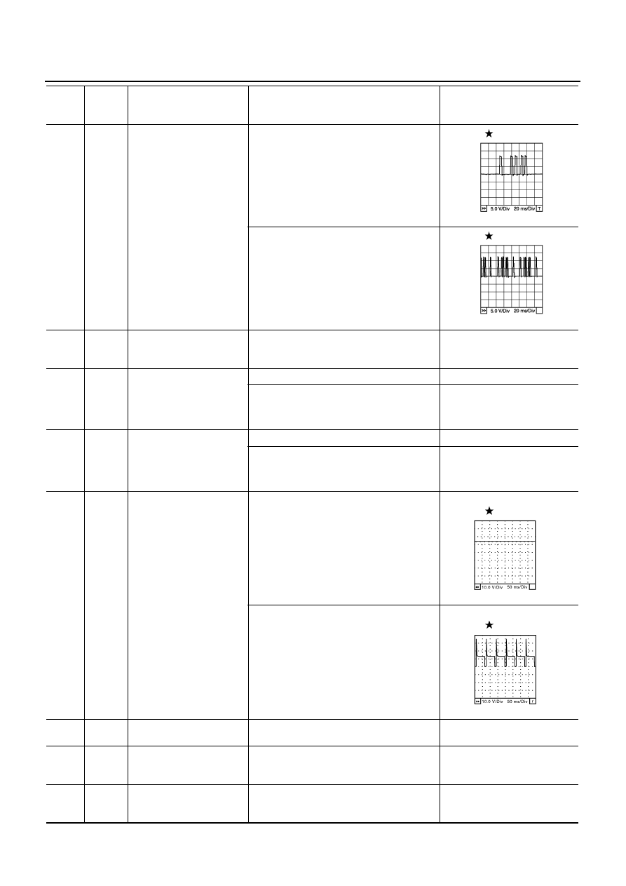
Ignition signal No. 5
Ignition signal No. 3
Ignition signal No. 1
Ignition signal No. 6
Ignition signal No. 4
Ignition signal No. 2
[Engine is running]
●
Warm-up condition
●
Idle speed
NOTE:
The pulse cycle changes depending on rpm
at idle
0 - 0.2V
[Engine is running]
●
Warm-up condition
●
Engine speed: 2,000 rpm
0.1 - 0.4V
66
B
Sensor ground
(Throttle position sensor)
[Engine is running]
●
Warm-up condition
●
Idle speed
Approximately 0V
67
B/W
Sensor ground
[Engine is running]
●
Warm-up condition
●
Idle speed
Approximately 0V
68
L/Y
Sensor power supply
(Power steering pressure
sensor)
[Ignition switch: ON]
Approximately 5V
TER-
MINAL
NO.
WIRE
COLOR
ITEM
CONDITION
DATA (DC Voltage)
PBIB0044E
PBIB0045E

EC-120
[VQ35DE]
TROUBLE DIAGNOSIS
69
R
Throttle position sensor 2
[Ignition switch: ON]
●
Engine stopped
●
Selector lever: D
●
Accelerator pedal: Fully released
Less than 4.75V
[Ignition switch: ON]
●
Engine stopped
●
Selector lever: D
●
Accelerator pedal: Fully depressed
More than 0.36V
70
L/R
Refrigerant pressure sensor
[Engine is running]
●
Warm-up condition
●
Both A/C switch and blower fan motor
switch: ON (Compressor operates)
1.0 - 4.0V
71
L/R
Battery current sensor
[Engine is running]
●
Battery: Fully charged*
●
Idle speed
Approximately 2.6 - 3.5V
73
Y/B
Engine coolant temperature
sensor
[Engine is running]
Approximately 0 - 4.8V
Output voltage varies with
engine coolant temperature.
74
W
Heated oxygen sensor 2
(bank 1)
[Engine is running]
●
Revving engine from idle to 3,000 rpm
quickly after the following conditions are met
–
Engine: After warming up
–
Keeping the engine speed between 3,500
and 4,000 rpm for 1 minute and at idle for 1
minute under no load
0 - Approximately 1.0V
78
B
Sensor ground
(Heated oxygen sensor)
[Engine is running]
●
Warm-up condition
●
Idle speed
Approximately 0V
82
W
Sensor ground
(APP sensor 1)
[Engine is running]
●
Warm-up condition
●
Idle speed
Approximately 0V
83
P
Sensor ground
(APP sensor 2)
[Engine is running]
●
Warm-up condition
●
Idle speed
Approximately 0V
85
V
Data link connector
[Ignition switch: ON]
●
CONSULT-II or GST: Disconnected
Approximately 5V - Battery volt-
age (11 - 14V)
86
P
CAN communication line
[Ignition switch: ON]
Approximately 1.1 - 2.3V
Output voltage varies with the
communication status.
90
L
Sensor power supply
(APP sensor 1)
[Ignition switch: ON]
Approximately 5V
91
BR
Sensor power supply
(APP sensor 2)
[Ignition switch: ON]
Approximately 5V
94
L
CAN communication line
[Ignition switch: ON]
Approximately 2.6 - 3.2V
Output voltage varies with the
communication status.
TER-
MINAL
NO.
WIRE
COLOR
ITEM
CONDITION
DATA (DC Voltage)
Нет комментариевНе стесняйтесь поделиться с нами вашим ценным мнением.
Текст