Infiniti M35/M45 Y50. Manual — part 291

VEHICLE SECURITY (THEFT WARNING) SYSTEM
BL-233
C
D
E
F
G
H
J
K
L
M
A
B
BL
Trouble Diagnosis Symptom Chart
NIS00204
*: Make sure the system is in the armed phase.
Procedure
Diagnostic procedure
Refer to page
Symptom
1
Vehicle security
system cannot be
set by ····
Door switch
Diagnostic Procedure 1 (Check door, hood and trunk switch)
Lock / unlock switch
Diagnostic Procedure 6 (Check door lock / unlock switch)
Door outside key
Diagnostic Procedure 3 (Check door key cylinder switch)
Intelligent Key
Check Intelligent Key.
—
If the above systems are “OK”, replace BCM.
Security indicator does not turn “ON”.
Diagnostic Procedure 2 (Check security indicator lamp)
If the above systems are “OK”, replace BCM.
2
* Vehicle security
system does not
alarm when ····
Any door is opened.
Diagnostic Procedure 1 (Check door, hood and trunk switch)
If the above systems are “OK”, replace BCM.
3
Vehicle security
alarm does not
activate.
Horn alarm
Diagnostic Procedure 4 (Check vehicle security horn alarm)
If the above systems are “OK”, replace BCM.
Head lamp alarm
Diagnostic Procedure 5 (Check head lamp alarm)
If the above systems are “OK”, replace BCM.
Hazard lamp
Diagnostic Procedure 7 (Check hazard lamp alarm)
If the above systems are “OK”, replace BCM.
4
Vehicle security
system cannot be
canceled by ····
Door outside key
Diagnostic Procedure 3 (Check door key cylinder switch)
If the above systems are “OK”, replace power window main
switch.
Intelligent Key
Check remote keyless entry function.
If the above systems are “OK”, replace BCM.
BL-234
VEHICLE SECURITY (THEFT WARNING) SYSTEM
Diagnostic Procedure 1
NIS00205
DOOR SWITCH CHECK
1.
CHECK DOOR SWITCH INPUT SIGNAL
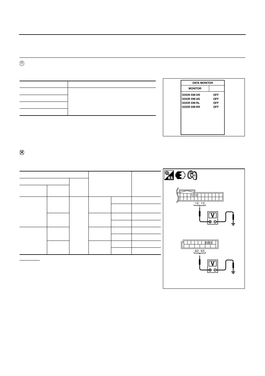
With CONSULT-II
Check door switches (“DOOR SW-DR”, “DOOR SW-AS”, “DOOR SW-RL” and “DOOR SW-RR”) in “DATA
MONITOR” mode with CONSULT-II.
Without CONSULT-II
1.
Turn ignition switch OFF.
2.
Check voltage between BCM connector and ground.
OK or NG
OK
>> Door switch circuit is OK.
NG
>> GO TO 2.
Monitor item
Condition
DOOR SW-DR
CLOSE
→
OPEN: OFF
→
ON
DOOR SW-AS
DOOR SW-RL
DOOR SW-RR
PIIA6469E
Terminals
Door condition
Voltage (V)
(Approx.)
(+)
(–)
BCM
connector
Terminal
M1
12
Ground
Front
passenger
side
OPEN
0
CLOSE
Battery voltage
13
Rear RH
side
OPEN
0
CLOSE
Battery voltage
M3
62
Driver side
OPEN
0
CLOSE
Battery voltage
63
Rear LH
side
OPEN
0
CLOSE
Battery voltage
PIIB6324E
VEHICLE SECURITY (THEFT WARNING) SYSTEM
BL-235
C
D
E
F
G
H
J
K
L
M
A
B
BL
2.
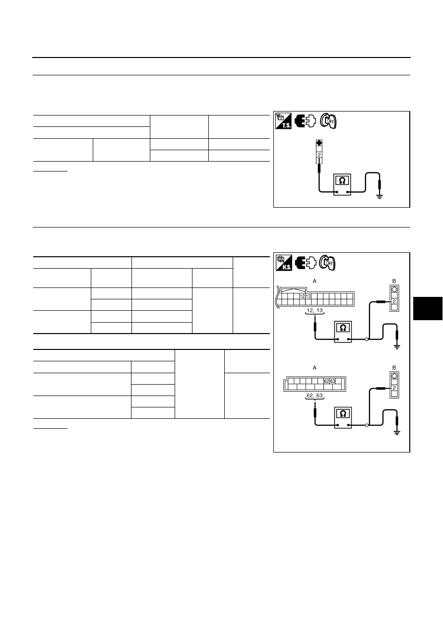
CHECK DOOR SWITCH
1.
Turn ignition switch OFF.
2.
Disconnect door switch connector.
3.
Check door switch.
OK or NG
OK
>> GO TO 3.
NG
>> Replace malfunction door switch.
3.
CHECK DOOR SWITCH CIRCUIT
1.
Disconnect BCM connector.
2.
Check continuity between BCM connector and door switch connector.
3.
Check continuity between BCM connector and ground.
OK or NG
OK
>> GO TO 4.
NG
>> Repair or replace harness between BCM and door
switch.
Terminal
Door switch
Continuity
Door switch
2
Ground part of
door switch
Pushed
No
Released
Yes
PIIB5977E
A
B
Continuity
BCM connector
Terminal
Door switch
connector
Terminal
M1
12
B424
2
Yes
13
B403
M3
62
B11
63
B53
A
Ground
Continuity
BCM connector
Terminal
M1
12
No
13
M3
62
63
PIIB6325E
BL-236
VEHICLE SECURITY (THEFT WARNING) SYSTEM
4.
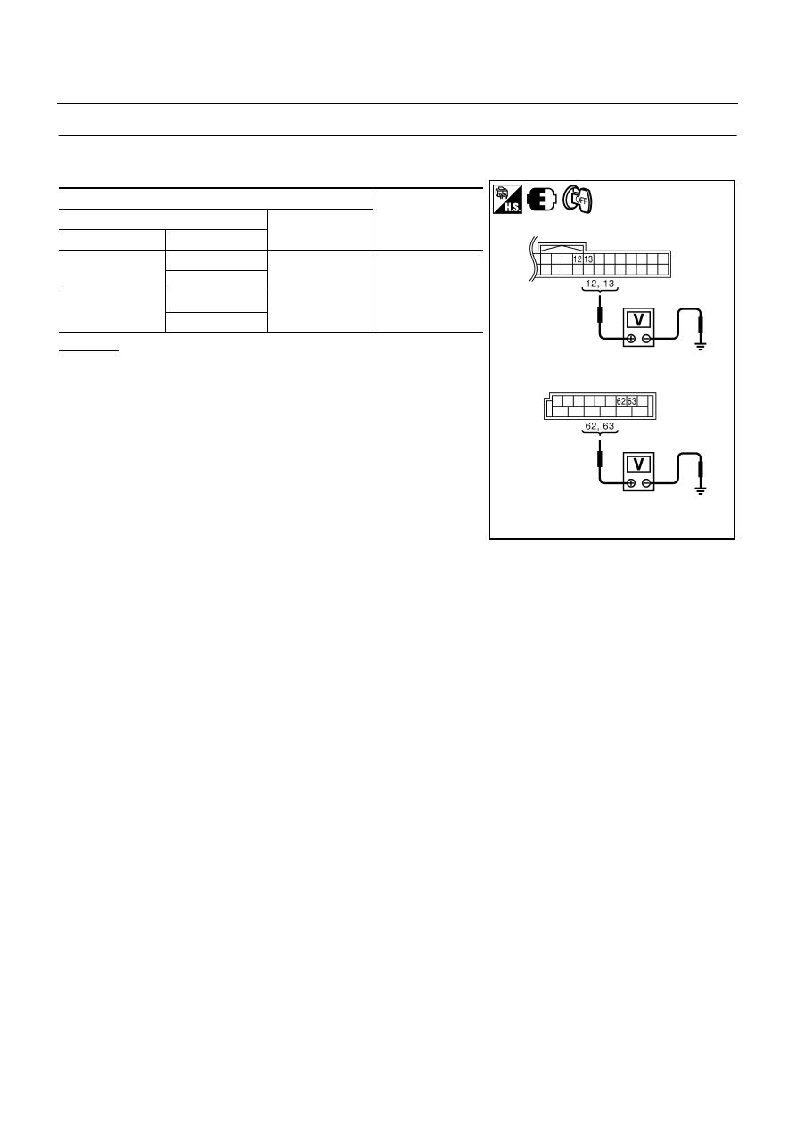
CHECK BCM OUTPUT SIGNAL
1.
Connect BCM connector.
2.
Check voltage between BCM connector and ground.
OK or NG
OK
>> Check the condition of harness and connector.
NG
>> Replace BCM.
Terminals
Voltage (V)
(Approx.)
(+)
(–)
BCM connector
Terminal
M1
12
Ground
Battery voltage
13
M3
62
63
PIIB6324E
Нет комментариевНе стесняйтесь поделиться с нами вашим ценным мнением.
Текст