Infiniti M35/M45 Y50. Manual — part 1134
AIR BREATHER HOSE
TF-43
C
E
F
G
H
I
J
K
L
M
A
B
TF
AIR BREATHER HOSE
PFP:31098
Removal and Installation
NDS000E3
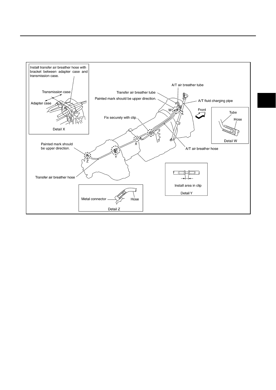
Refer to the figure for air breather hose removal and installation information.
CAUTION:
●
Make sure there are no pinched or restricted areas on the air breather hose caused by bending or
winding when installing it.
●
Be sure to insert air breather hose to transfer tube (metal connector) until hose end reaches the
tube's base and another hose end reaches the tube bend R portion of A/T fluid charging pipe.
SDIA2408E
TF-44
TRANSFER ASSEMBLY
TRANSFER ASSEMBLY
PFP:33100
Removal and Installation
NDS000E4
REMOVAL
1.
Remove exhaust front tube with power tool. Refer to
2.
Remove front and rear propeller shaft. Refer to
3.
Disconnect transfer assembly harness connector and separate harness from transfer assembly.
4.
Remove air breather hose. Refer to
5.
Remove control rod. Refer to
AT-226, "Control Rod Removal and Installation"
.
6.
Support transfer assembly and transmission assembly with a jack.
7.
Remove rear engine mounting member and engine mounting insulator with power tool. Refer to
8.
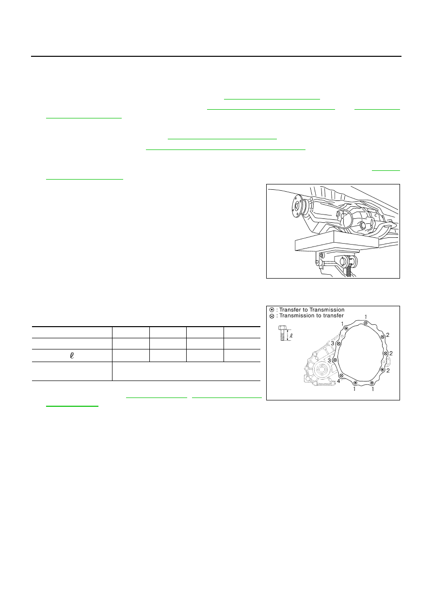
Lower jack to the position where the top transfer mounting bolts
can be removed.
9.
Remove transfer mounting bolts with power tool and separate
transfer from transmission.
CAUTION:
Secure transfer assembly and transmission assembly to a
jack.
INSTALLATION
Note the following, and install in the reverse order of removal.
●
When installing the transfer to the transmission, install the
mounting bolts following the standard below.
●
After the installation, check the fluid level, fluid leakage and the
A/T positions. Refer to
PDIA0560J
Bolt No.
1
2
3
4
Quantity
4
3
2
1
Bolt length “
” mm (in)
75 (2.95)
45 (1.77)
40 (1.57)
30 (1.18)
Tightening torque
N·m (kg-m, ft-lb)
37 (3.8, 27)
SDIA2284E
TRANSFER ASSEMBLY
TF-45
C
E
F
G
H
I
J
K
L
M
A
B
TF
Disassembly and Assembly
NDS000E5
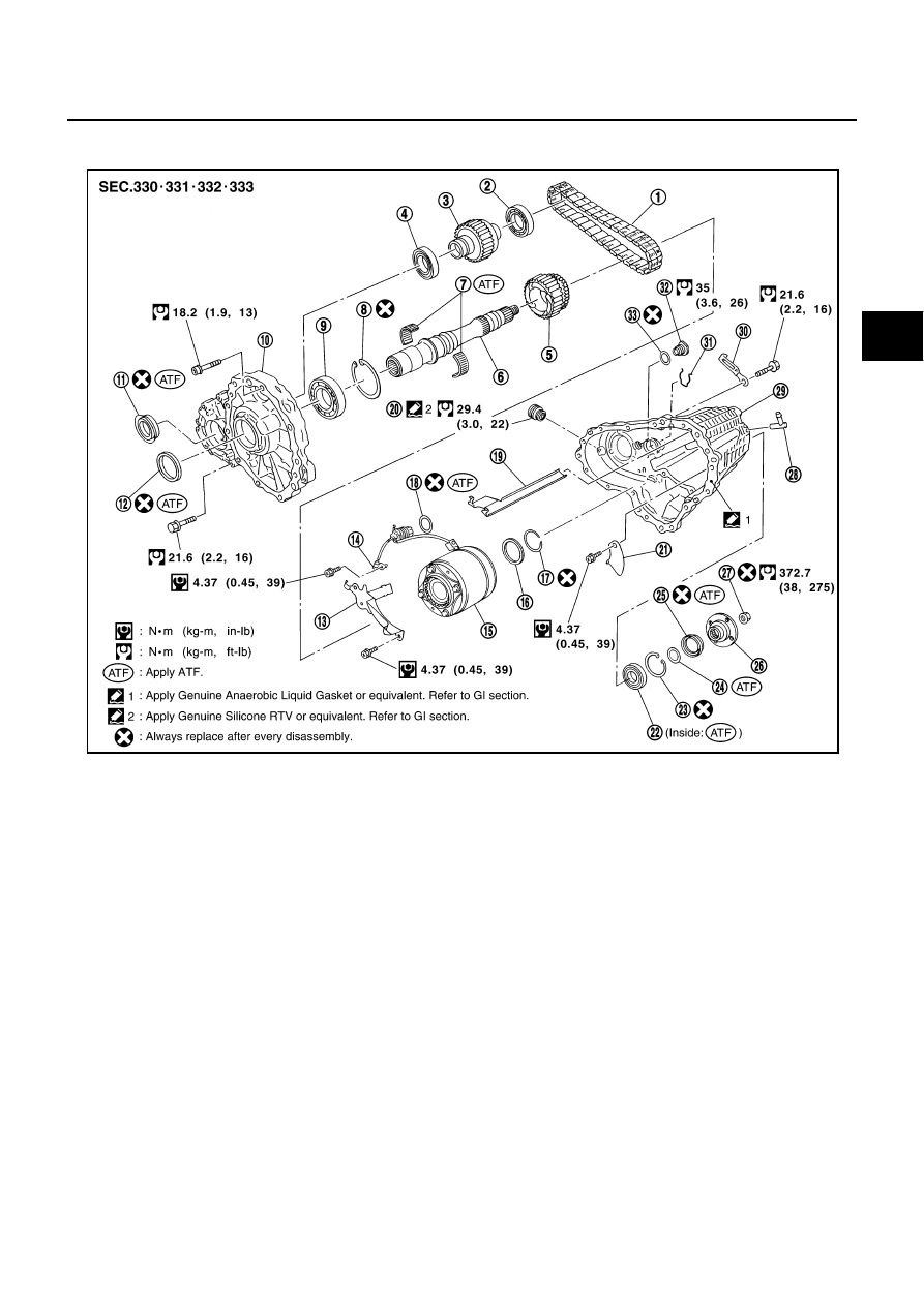
COMPONENTS
*: This may not be used for December
′
06 models or later.
1.
Drive chain
2.
Front drive shaft rear bearing
3.
Front drive shaft
4.
Front drive shaft front bearing
5.
Sprocket
6.
Mainshaft
7.
Needle bearing
8.
Snap ring
9.
Mainshaft bearing
10. Front case
11.
Front oil seal
12. Mainshaft oil seal
13. Oil cover
14. Temperature sensor*
15. Electric controlled coupling
16. Spacer
17. Snap ring
18. O-ring
19. Oil gutter
20. Drain plug
21. Baffle plate
22. Rear bearing
23. Snap ring
24. Spacer
25. Rear oil seal
26. Companion flange
27. Self-lock nut
28. Breather tube
29. Rear case
30. Harness bracket
31. Retainer
32. Filler plug
33. Gasket
PDIA0244E
TF-46
TRANSFER ASSEMBLY
DISASSEMBLY
Front Case and Rear Case
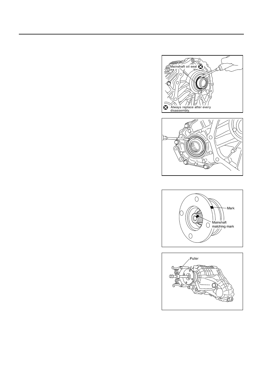
1.
Remove drain plug and filler plug.
2.
Remove mainshaft oil seal from front case, using a flat-bladed
screwdriver.
CAUTION:
Be careful not to damage the front case and mainshaft.
3.
Remove front oil seal from front case, using a flat-bladed screw-
driver.
CAUTION:
Be careful not to damage the front case and front drive
shaft.
4.
Remove self-lock nut.
5.
Put a matching mark on the end of mainshaft. The mark should
be in line with the mark on the companion flange.
CAUTION:
For matching mark, use paint. Do not damage mainshaft.
6.
Remove companion flange, using a puller.
CAUTION:
Be careful not to damage the companion flange.
PDIA0253E
PDIA0255E
SDIA2378E
PDIA0258E
Нет комментариевНе стесняйтесь поделиться с нами вашим ценным мнением.
Текст