Infiniti M35/M45 Y50. Manual — part 883

HEADLAMP (FOR USA) - XENON TYPE -
LT-77
C
D
E
F
G
H
I
J
L
M
A
B
LT
ASSEMBLY
Note the following, and installation is the reverse order of removal.
CAUTION:
●
When HID control unit is removed, reinstall it securely and avoid any looseness.
●
After installing bulb, be sure to install plastic cap and bulb socket securely to insure watertight-
ness
HID control unit mounting screw
: 3.2 N·m (0.32 kg-m, 28 in-lb)
LT-78
HEADLAMP (FOR CANADA) - DAYTIME LIGHT SYSTEM -
HEADLAMP (FOR CANADA) - DAYTIME LIGHT SYSTEM -
PFP:26010
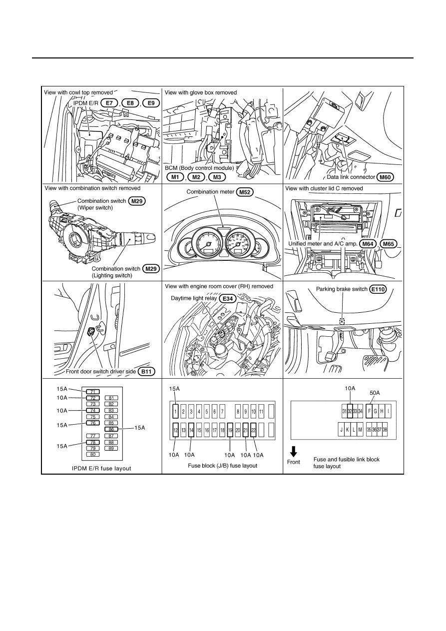
Component Parts and Harness Connector Location
NKS003P9
System Description
NKS003PA
DAYTIME LIGHT SYSTEM turns on daytime light lamps while driving. Daytime light lamps are not turned on if
engine is activated with parking brake on. Take off parking brake to turn on daytime light lamps. The lamps
turn off when lighting switch is in the 2ND position or AUTO position (Head lamp is “ON”) and when lighting
switch is in the PASSING position. (Daytime light lamps are not turned off only by parking brake itself.)
A parking brake signal and engine run or stop signal are sent to BCM (body control module) by CAN commu-
nication line, and control daytime light system.
PKID0500E
HEADLAMP (FOR CANADA) - DAYTIME LIGHT SYSTEM -
LT-79
C
D
E
F
G
H
I
J
L
M
A
B
LT
OUTLINE
Power is supplied at all times
●
to headlamp high relay, located in IPDM E/R (intelligent power distribution module engine room) and
●
to headlamp low relay, located in IPDM E/R, from battery direct,
●
through 15A fuse (No. 71, located in IPDM E/R)
●
to CPU (central processing unit), located in IPDM E/R,
●
through 15A fuse (No. 78, located in IPDM E/R)
●
to CPU, located in IPDM E/R,
●
through 50A fusible link (letter F, located in fuse and fusible link block)
●
to BCM terminal 55,
●
through 10A fuse [No. 21, located in fuse block (J/B)]
●
to BCM terminal 42 and
●
to combination meter terminal 23,
●
through 10A fuse (No. 32, located in IPDM E/R)
●
to daytime light relay terminals 2 and 5,
●
through 10A fuse [No. 19, located in fuse block (J/B)]
●
to unified meter and A/C amp. terminal 54,
●
through 10A fuse [No. 22, located in fuse block (J/B)]
●
to key slot terminal 1.
When the ignition switch is in ON or START position, power is supplied
●
to CPU, located in IPDM E/R,
●
through 15A fuse [No. 1, located in fuse block (J/B)]
●
to BCM terminal 38,
●
through 10A fuse [No. 14, located in fuse block (J/B)]
●
to combination meter terminal 12,
●
through 10A fuse [No. 12, located in fuse block (J/B)]
●
to unified meter and A/C amp. terminal 53.
Ground is supplied
●
to BCM terminal 52
●
to combination meter terminals 9, 10, and 11
●
to unified meter and A/C amp. terminal 55 and 71
●
to push-button ignition switch (push switch) terminal 1
●
to key slot terminal 8
●
through grounds M16 and M70,
●
to IPDM E/R terminals 38 and 51
●
through grounds E22 and E43.
LT-80
HEADLAMP (FOR CANADA) - DAYTIME LIGHT SYSTEM -
HEADLAMP OPERATION
Low Beam Operation
With the lighting switch in 2ND position, the BCM receives input signal requesting the headlamps to illuminate.
This input signal is communicated to IPDM E/R across the CAN communication lines. The CPU located in the
IPDM E/R controls the headlamp low relay coil, which when energized, directs power
●
through 15A fuse (No. 76, located in IPDM E/R)
●
through IPDM E/R terminal 20
●
to front combination lamp RH terminal 8,
●
through 15A fuse (No. 86, located in IPDM E/R)
●
through IPDM E/R terminal 30
●
to front combination lamp LH terminal 8.
Ground is supplied
●
to front combination lamp RH terminal 4
●
to front combination lamp LH terminal 4
●
through grounds E22 and E43.
With power and ground supplied, low beam headlamps illuminate.
High Beam Operation (When Daytime Light Does Not Operate)/Flash-to-Pass Operation
With the lighting switch in 2ND position and placed in HIGH BEAM or PASSING position, the BCM receives
input signal requesting headlamp high beams to illuminate. High beam request signal is communicated to the
IPDM E/R across the CAN communication lines. The CPU located in the IPDM E/R controls headlamp high
relay coil and low relay coil, which when energized, directs power
●
through 10A fuse (No. 72, located in IPDM E/R)
●
through IPDM E/R terminal 27
●
through front combination lamp RH terminals 6 and 2
●
to daytime light relay terminal 3,
●
through 10A fuse (No. 74, located in IPDM E/R)
●
through IPDM E/R terminal 28
●
to front combination lamp LH terminal 6,
●
through 15A fuse (No. 76, located in IPDM E/R)
●
through IPDM E/R terminal 20
●
to front combination lamp RH terminal 8,
●
through 15A fuse (No. 86, located in IPDM E/R)
●
through IPDM E/R terminal 30
●
to front combination lamp LH terminal 8.
Ground is supplied
●
to daytime light relay terminal 4
●
to front combination lamp RH terminal 4
●
to front combination lamp LH terminal 2
●
to front combination lamp LH terminal 4
●
through grounds E22 and E43.
With the power and ground supplied, the headlamp high beam and low headlamp illuminate.
High beam indicator illuminates when combination meter receives input signal requesting high beam indicator
to illuminate. This is communicated to BCM across the CAN communication lines.
Нет комментариевНе стесняйтесь поделиться с нами вашим ценным мнением.
Текст