Infiniti M35/M45 Y50. Manual — part 862
TROUBLE DIAGNOSIS
LAN-97
[CAN]
C
D
E
F
G
H
I
J
L
M
A
B
LAN
Steering Angle Sensor Branch Line Circuit
NKS004GH
INSPECTION PROCEDURE
1.
CHECK CONNECTOR
1.
Turn the ignition switch OFF.
2.
Disconnect the battery cable from the negative terminal.
3.
Check the terminals and connectors of the steering angle sensor for damage, bend and loose connection
(unit side and connector side).
OK or NG
OK
>> GO TO 2.
NG
>> Repair the terminal and connector.
2.
CHECK HARNESS FOR OPEN CIRCUIT
1.
Disconnect the connector of steering angle sensor.
2.
Check the resistance between the steering angle sensor harness connector terminals.
OK or NG
OK
>> GO TO 3.
NG
>> Repair the steering angle sensor branch line.
3.
CHECK POWER SUPPLY AND GROUND CIRCUIT
Check the power supply and the ground circuit of the steering angle sensor. Refer to
(Models with VDC),
OK or NG
OK
>>
●
Present error: Replace the steering angle sensor. Refer to
BRC-60, "Removal and Installation"
●
Past error: Error was detected in the steering angle sensor branch line.
NG
>> Repair the power supply and the ground circuit.
Low Tire Pressure Warning Control Unit Branch Line Circuit
NKS004H3
INSPECTION PROCEDURE
1.
CHECK CONNECTOR
1.
Turn the ignition switch OFF.
2.
Disconnect the battery cable from the negative terminal.
3.
Check the terminals and connectors of the low tire pressure warning control unit for damage, bend and
loose connection (unit side and connector side).
OK or NG
OK
>> GO TO 2.
NG
>> Repair the terminal and connector.
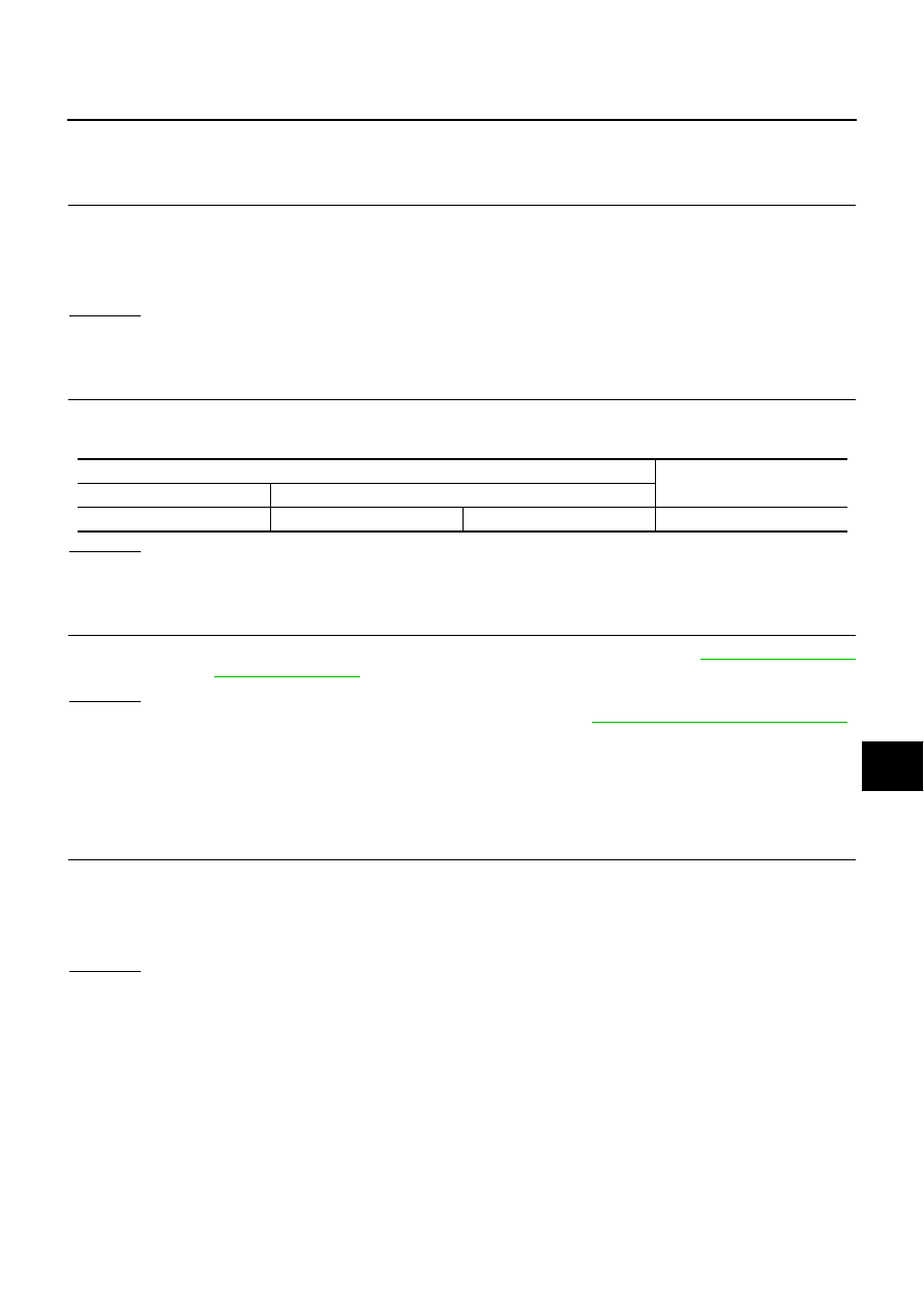
Steering angle sensor harness connector
Resistance (
Ω
)
Connector No.
Terminal No.
M47
4
5
Approx. 54 – 66
LAN-98
[CAN]
TROUBLE DIAGNOSIS
2.
CHECK HARNESS FOR OPEN CIRCUIT
1.
Disconnect the connector of low tire pressure warning control unit.
2.
Check the resistance between the low tire pressure warning control unit harness connector terminals.
OK or NG
OK
>> GO TO 3.
NG
>> Repair the low tire pressure warning control unit branch line.
3.
CHECK POWER SUPPLY AND GROUND CIRCUIT
Check the power supply and the ground circuit of the low tire pressure warning control unit. Refer to
OK or NG
OK
>>
●
Present error: Replace the low tire pressure warning control unit. Refer to
Pressure Warning Control Unit"
●
Past error: Error was detected in the low tire pressure warning control unit branch line.
NG
>> Repair the power supply and the ground circuit.
RAS Control Unit Branch Line Circuit
NKS004H4
INSPECTION PROCEDURE
1.
CHECK CONNECTOR
1.
Turn the ignition switch OFF.
2.
Disconnect the battery cable from the negative terminal.
3.
Check the terminals and connectors of the RAS control unit for damage, bend and loose connection (unit
side and connector side).
OK or NG
OK
>> GO TO 2.
NG
>> Repair the terminal and connector.
2.
CHECK HARNESS FOR OPEN CIRCUIT
1.
Disconnect the connector of RAS control unit.
2.
Check the resistance between the RAS control unit harness connector terminals.
OK or NG
OK
>> GO TO 3.
NG
>> Replace the body No. 2 harness.
3.
CHECK POWER SUPPLY AND GROUND CIRCUIT
Check the power supply and the ground circuit of the RAS control unit. Refer to
OK or NG
OK
>>
●
Present error: Replace the RAS control unit.
●
Past error: Error was detected in the RAS control unit branch line.
NG
>> Repair the power supply and the ground circuit.
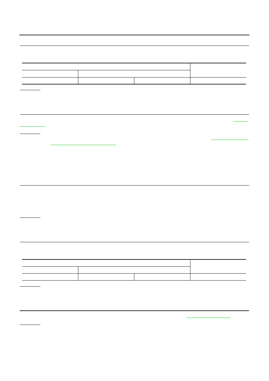
Low tire pressure warning control unit harness connector
Resistance (
Ω
)
Connector No.
Terminal No.
M19
15
16
Approx. 54 – 66
RAS control unit harness connector
Resistance (
Ω
)
Connector No.
Terminal No.
B476
1
8
Approx. 54 – 66
TROUBLE DIAGNOSIS
LAN-99
[CAN]
C
D
E
F
G
H
I
J
L
M
A
B
LAN
Pre-Crash Seat Belt Control Unit Branch Line Circuit
NKS004H5
INSPECTION PROCEDURE
1.
CHECK CONNECTOR
1.
Turn the ignition switch OFF.
2.
Disconnect the battery cable from the negative terminal.
3.
Check the terminals and connectors of the pre-crash seat belt control unit for damage, bend and loose
connection (unit side and connector side).
OK or NG
OK
>> GO TO 2.
NG
>> Repair the terminal and connector.
2.
CHECK HARNESS FOR OPEN CIRCUIT
1.
Disconnect the connector of pre-crash seat belt control unit.
2.
Check the resistance between the pre-crash seat belt control unit harness connector terminals.
OK or NG
OK
>> GO TO 3.
NG
>> Replace the body harness.
3.
CHECK POWER SUPPLY AND GROUND CIRCUIT
Check the power supply and the ground circuit of the pre-crash seat belt control unit. Refer to
OK or NG
OK
>>
●
Present error: Replace the pre-crash seat belt control unit. Refer to
Installation of Pre-Crash Seat Belt Control Unit"
.
●
Past error: Error was detected in the pre-crash seat belt control unit branch line.
NG
>> Repair the power supply and the ground circuit.
Driver Seat Control Unit Branch Line Circuit
NKS004GB
INSPECTION PROCEDURE
1.
CHECK CONNECTOR
1.
Turn the ignition switch OFF.
2.
Disconnect the battery cable from the negative terminal.
3.
Check the following terminals and connectors for damage, bend and loose connection (unit side and con-
nector side).
–
Driver seat control unit connector
–
Harness connector B202
–
Harness connector B15
OK or NG
OK
>> GO TO 2.
NG
>> Repair the terminal and connector.
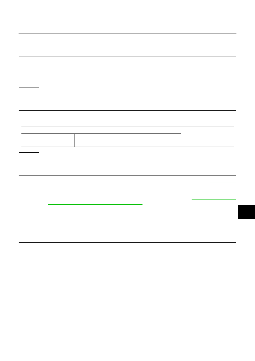
Pre-crash seat belt control unit harness connector
Resistance (
Ω
)
Connector No.
Terminal No.
B142
24
22
Approx. 54 – 66
LAN-100
[CAN]
TROUBLE DIAGNOSIS
2.
CHECK HARNESS FOR OPEN CIRCUIT
1.
Disconnect the connector of driver seat control unit.
2.
Check the resistance between the driver seat control unit harness connector terminals.
OK or NG
OK
>> GO TO 3.
NG
>> Replace the body harness.
3.
CHECK POWER SUPPLY AND GROUND CIRCUIT
Check the power supply and the ground circuit of the driver seat control unit. Refer to
OK or NG
OK
>>
●
Present error: Replace the driver seat control unit.
●
Past error: Error was detected in the driver seat control unit branch line.
NG
>> Repair the power supply and the ground circuit.
ABS Actuator and Electric Unit (Control Unit) Branch Line Circuit
NKS004GM
INSPECTION PROCEDURE
1.
CHECK CONNECTOR
1.
Turn the ignition switch OFF.
2.
Disconnect the battery cable from the negative terminal.
3.
Check the terminals and connectors of the ABS actuator and electric unit (control unit) for damage, bend
and loose connection (unit side and connector side).
OK or NG
OK
>> GO TO 2.
NG
>> Repair the terminal and connector.
2.
CHECK HARNESS FOR OPEN CIRCUIT
1.
Disconnect the connector of ABS actuator and electric unit (control unit).
2.
Check the resistance between the ABS actuator and electric unit (control unit) harness connector termi-
nals.
OK or NG
OK
>> GO TO 3.
NG
>> Repair the ABS actuator and electric unit (control unit) branch line.
3.
CHECK POWER SUPPLY AND GROUND CIRCUIT
Check the power supply and the ground circuit of the ABS actuator and electric unit (control unit). Refer to
OK or NG
OK
>>
●
Present error: Replace the ABS actuator and electric unit (control unit). Refer to
●
Past error: Error was detected in the ABS actuator and electric unit (control unit) branch line.
NG
>> Repair the power supply and the ground circuit.
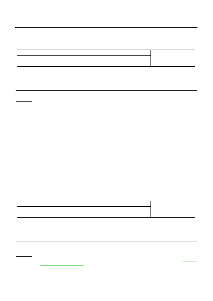
Driver seat control unit harness connector
Resistance (
Ω
)
Connector No.
Terminal No.
B204
3
19
Approx. 54 – 66
ABS actuator and electric unit (control unit) harness connector
Resistance (
Ω
)
Connector No.
Terminal No.
E30
35
14
Approx. 54 – 66
Нет комментариевНе стесняйтесь поделиться с нами вашим ценным мнением.
Текст