Infiniti M35/M45 Y50. Manual — part 218
TROUBLE DIAGNOSIS
AV-249
[WITH MOBILE ENTERTAINMENT SYSTEM]
C
D
E
F
G
H
I
J
L
M
A
B
AV
TROUBLE DIAGNOSIS
PFP:00004
Multifunction Switch Cannot Be Operated
NKS004B2
1.
PERFORM CONSULT-II SELF-DIAGNOSIS
Perform CONSULT-II self-diagnosis and check the malfunction. Refer to
Is there a malfunction?
YES
>> Refer to
AV-103, "Display Item of SELF-DIAG RESULTS"
.
NO
>> Replace multifunction switch
RGB Image Is Not Displayed
NKS004B3
RGB IMAGE IS NOT DISPLAYED ON FRONT AND REAR DISPLAYS
1.
DIAGNOSIS USING CONSULT-II
Start CONSULT-II, and make sure that “MULTI AV” is displayed on SELECT SYSTEM screen. Refer to
.
OK or NG
OK
>> Refer to
.
NG
>> Check AV (NAVI) control unit power supply and ground circuit.
ONLY FRONT DISPLAY
1.
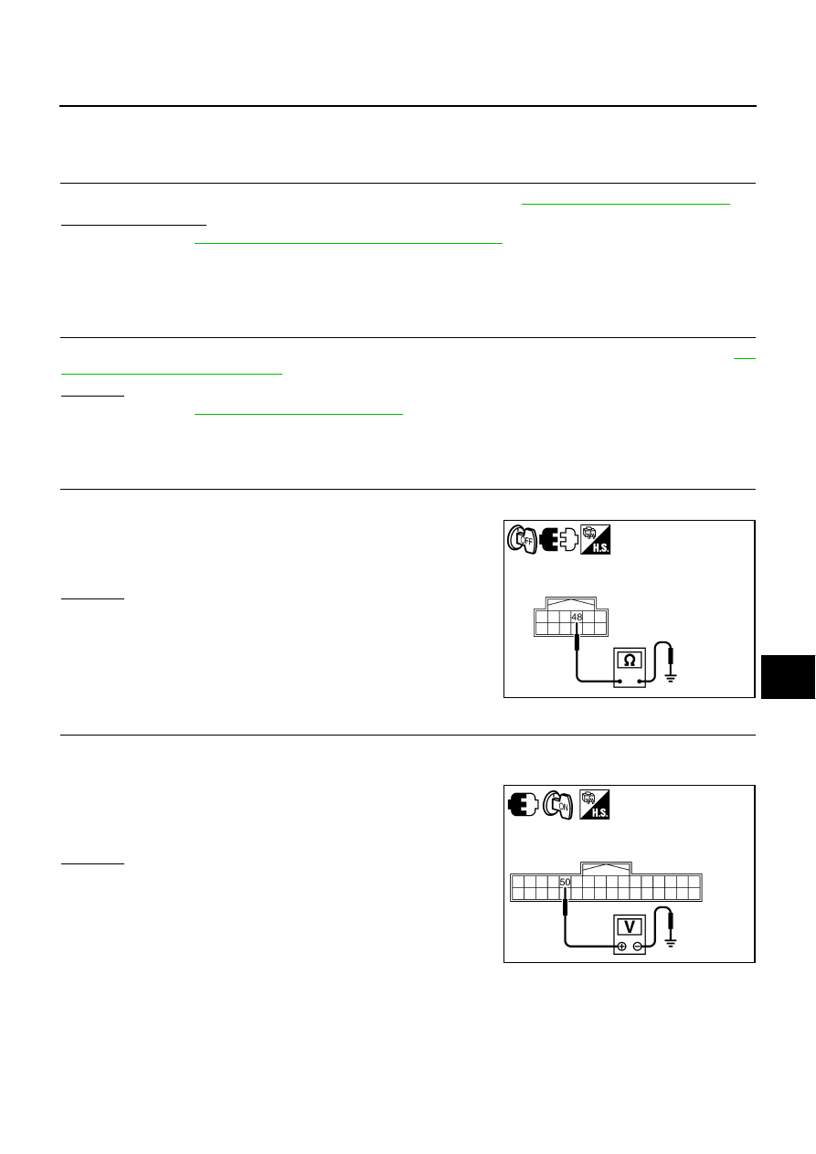
CHECK HARNESS BETWEEN AV (NAVI) CONTROL UNIT AND VIDEO DISTRIBUTOR
1.
Disconnect AV (NAVI) control unit connector and video distributor connector.
2.
Check continuity between video distributor harness connector
M207 terminal 48 and ground.
OK or NG
OK
>> GO TO 2.
NG
>> Repair harness or connector.
2.
CHECK RGB AREA SIGNAL FOR AV (NAVI) CONTROL UNIT
1.
Connect AV (NAVI) control unit connector.
2.
Turn ignition switch ON.
3.
Check voltage between AV (NAVI) control unit harness connec-
tor M210 terminal 50 and ground.
OK or NG
OK
>> GO TO 3.
NG
>> Replace AV (NAVI) control unit.
48 – Ground
: Continuity should not exist.
SKIB4593E
50 – Ground
: Approx. 5 V
SKIB6893E
AV-250
[WITH MOBILE ENTERTAINMENT SYSTEM]
TROUBLE DIAGNOSIS
3.
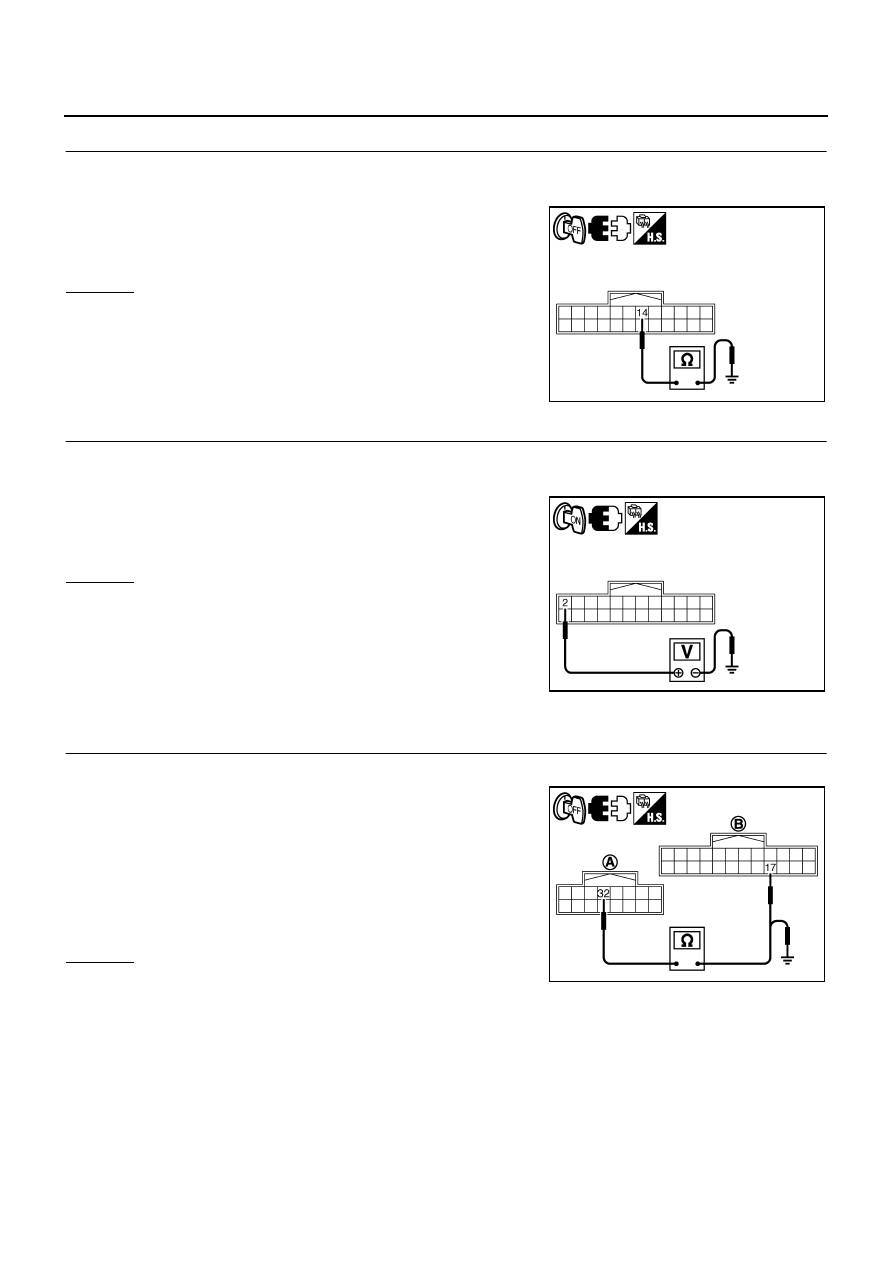
CHECK HARNESS BETWEEN VIDEO DISTRIBUTOR AND FRONT DISPLAY UNIT
1.
Turn ignition switch OFF.
2.
Disconnect front display unit connector.
3.
Check continuity between video distributor harness connector
M205 terminal 14 and ground.
OK or NG
OK >> GO
TO
4.
NG
>> Repair harness or connector.
4.
CHECK FRONT DISPLAY UNIT
1.
Connect front display unit connector.
2.
Turn ignition switch ON.
3.
Check voltage between front display unit harness connector
M203 terminal 2 and ground.
OK or NG
OK
>> Replace video distributor.
NG
>> Replace front display unit.
ONLY REAR DISPLAY
1.
CHECK HARNESS BETWEEN VIDEO DISTRIBUTOR AND REAR DISPLAY UNIT
1.
Disconnect video distributor connector and rear display unit connector.
2.
Check continuity between video distributor harness connector
(A) M206 terminal 32 and rear display unit harness connector
(B) R102 terminal 17.
3.
Check continuity between video distributor harness connector
(A) M206 terminal 32 and ground.
OK or NG
OK
>> GO TO 2.
NG
>> Repair harness or connector.
14 – Ground
: Continuity should not exist.
SKIB4595E
2 – Ground
: Approx. 5 V
SKIB4596E
32 – 17
: Continuity should exist.
32 – Ground
: Continuity should not exist.
SKIB4597E

TROUBLE DIAGNOSIS
AV-251
[WITH MOBILE ENTERTAINMENT SYSTEM]
C
D
E
F
G
H
I
J
L
M
A
B
AV
2.
CHECK RGB AREA SIGNAL
1.
Connect video distributor connector.
2.
Turn ignition switch ON.
3.
Check voltage between rear display unit harness connector
R102 terminal 17 and ground.
OK or NG
OK
>> Replace rear display unit.
NG
>> Replace video distributor.
RGB Screen Is Rolling.
NKS004B4
ONLY FRONT DISPLAY
1.
CHECK REAR DISPLAY IMAGE
Make sure that the rear display image is purple (magenta) tint.
Is it purple (magenta) tint?
YES
>> GO TO 2.
NO
>> GO TO 4.
2.
CHECK HARNESS BETWEEN VIDEO DISTRIBUTOR AND AV (NAVI) CONTROL UNIT
1.
Turn ignition switch OFF.
2.
Disconnect video distributor connector and AV (NAVI) control unit connector.
3.
Check continuity between video distributor harness connector
(A) M207 terminal 45 and AV (NAVI) control unit harness con-
nector (B) M210 terminal 45.
4.
Check continuity between video distributor harness connector
(A) M207 terminal 45 and ground.
OK or NG
OK
>> GO TO 3.
NG
>> Repair harness or connector.
17 – Ground
: Approx. 5 V
SKIB4598E
45 – 45
: Continuity should exist.
45 – Ground
: Continuity should not exist.
SKIB4599E
AV-252
[WITH MOBILE ENTERTAINMENT SYSTEM]
TROUBLE DIAGNOSIS
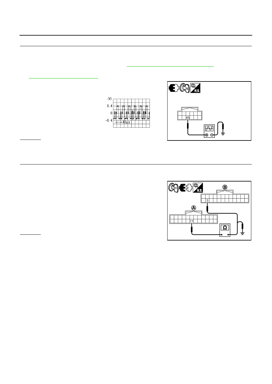
3.
CHECK RGB SIGNAL (G: GREEN)
1.
Connect video distributor connector and AV (NAVI) control unit connector.
2.
Turn ignition switch ON.
3.
Start Confirmation/Adjustment mode. Refer to
AV-231, "Confirmation/Adjustment Mode"
.
4.
Display color bar by selecting “Display Color Spectrum Bar” on DISPLAY DIAGNOSIS screen. Refer to
5.
Check signal between video distributor harness connector M207
terminal 45 and ground.
OK or NG
OK
>> Replace video distributor.
NG
>> Replace AV (NAVI) control unit.
4.
CHECK HARNESS BETWEEN VIDEO DISTRIBUTOR AND FRONT DISPLAY UNIT
1.
Turn ignition switch OFF.
2.
Disconnect video distributor connector and front display unit connector.
3.
Check continuity between video distributor harness connector
(A) M205 terminal 11 and front display unit harness connector
(B) M203 terminal 3.
4.
Check continuity between video distributor harness connector
(A) M205 terminal 11 and ground.
OK or NG
OK
>> GO TO 5.
NG
>> Repair harness or connector.
45 – Ground:
SKIB4600E
SKIB2236J
11 – 3
: Continuity should exist.
11 – Ground
: Continuity should not exist.
SKIB4601E
Нет комментариевНе стесняйтесь поделиться с нами вашим ценным мнением.
Текст