Infiniti M35/M45 Y50. Manual — part 596

TROUBLE DIAGNOSIS FOR INTERMITTENT INCIDENT
EC-857
[VK45DE]
C
D
E
F
G
H
I
J
K
L
M
A
EC
TROUBLE DIAGNOSIS FOR INTERMITTENT INCIDENT
PFP:00006
Description
NBS005AV
Intermittent incidents may occur. In many cases, the malfunction resolves itself (the part or circuit function
returns to normal without intervention). It is important to realize that the symptoms described in the customer's
complaint often do not recur on (1st trip) DTC visits. Realize also that the most frequent cause of intermittent
incidents occurrences is poor electrical connections. Because of this, the conditions under which the incident
occurred may not be clear. Therefore, circuit checks made as part of the standard diagnostic procedure may
not indicate the specific malfunctioning area.
Common Intermittent Incidents Report Situations
Diagnostic Procedure
NBS005AW
1.
INSPECTION START
Erase (1st trip) DTCs. Refer to
EC-770, "HOW TO ERASE EMISSION-RELATED DIAGNOSTIC INFORMA-
>> GO TO 2.
2.
CHECK GROUND TERMINALS
Check ground terminals for corroding or loose connection.
Refer to
.
OK or NG
OK
>> GO TO 3.
NG
>> Repair or replace.
3.
SEARCH FOR ELECTRICAL INCIDENT
Perform
GI-28, "How to Perform Efficient Diagnosis for an Electrical Incident"
, “INCIDENT SIMULATION
TESTS”.
OK or NG
OK
>> GO TO 4.
NG
>> Repair or replace.
4.
CHECK CONNECTOR TERMINALS
Refer to
GI-25, "How to Check Terminal"
, “HOW TO PROBE CONNECTORS”, “How to Check Enlarged Con-
tact Spring of Terminal”.
OK or NG
OK
>> INSPECTION END
NG
>> Repair or replace connector.
STEP in Work Flow
Situation
2
The CONSULT-II is used. The SELF-DIAG RESULTS screen shows time data other than [0] or [1t].
3 or 4
The symptom described by the customer does not recur.
5
(1st trip) DTC does not appear during the DTC Confirmation Procedure.
10
The Diagnostic Procedure for PXXXX does not indicate the malfunctioning area.
EC-858
[VK45DE]
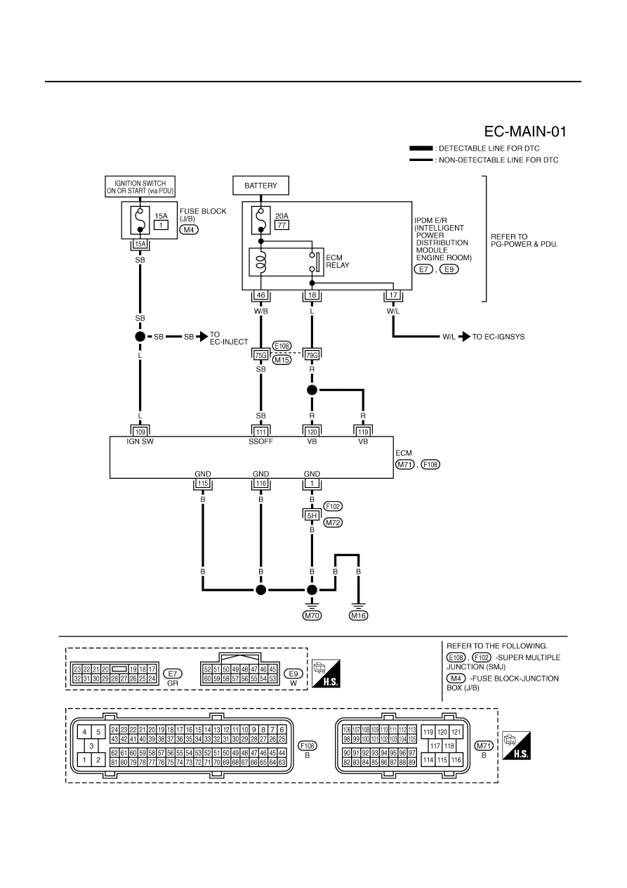
POWER SUPPLY AND GROUND CIRCUIT
POWER SUPPLY AND GROUND CIRCUIT
PFP:24110
Wiring Diagram
NBS005AX
TBWT1010E
POWER SUPPLY AND GROUND CIRCUIT
EC-859
[VK45DE]
C
D
E
F
G
H
I
J
K
L
M
A
EC
Specification data are reference values and are measured between each terminal and ground.
CAUTION:
Do not use ECM ground terminals when measuring input/output voltage. Doing so may result in dam-
age to the ECM's transistor. Use a ground other than ECM terminals, such as the ground.
Diagnostic Procedure
NBS005AY
1.
INSPECTION START
Start engine.
Is engine running?
Yes or No
Yes
>> GO TO 8.
No
>> GO TO 2.
2.
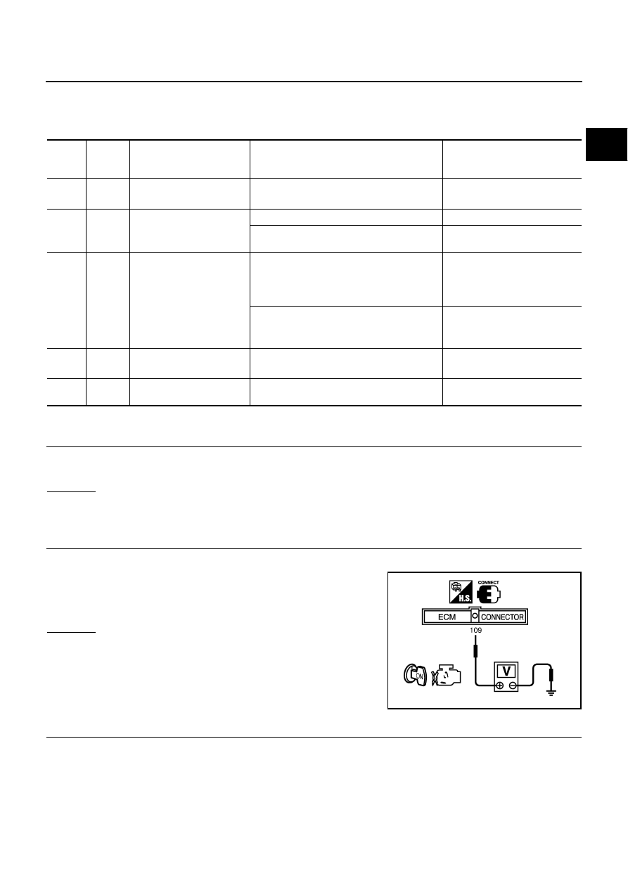
CHECK ECM POWER SUPPLY CIRCUIT-I
1.
Turn ignition switch OFF and then ON.
2.
Check voltage between ECM terminal 109 and ground with
CONSULT-II or tester.
OK or NG
OK
>> GO TO 4.
NG
>> GO TO 3.
3.
DETECT MALFUNCTIONING PART
Check the following.
●
Fuse block (J/B) connector M4
●
15A fuse
●
Harness for open or short between ECM and fuse
>> Repair open circuit or short to ground or short to power in harness or connectors.
TER-
MINAL
NO.
WIRE
COLOR
ITEM
CONDITION
DATA (DC Voltage)
1
B
ECM ground
[Engine is running]
●
Idle speed
Body ground
109
L
Ignition switch
[Ignition switch: OFF]
0V
[Ignition switch: ON]
BATTERY VOLTAGE
(11 - 14V)
111
SB
ECM relay
(Self shut-off)
[Engine is running]
[Ignition switch: OFF]
●
For a few seconds after turning ignition
switch OFF
0 - 1.5V
[Ignition switch: OFF]
●
More than a few seconds after turning igni-
tion switch OFF
BATTERY VOLTAGE
(11 - 14V)
115
116
B
B
ECM ground
[Engine is running]
●
Idle speed
Body ground
119
120
R
R
Power supply for ECM
[Ignition switch: ON]
BATTERY VOLTAGE
(11 - 14V)
Voltage: Battery voltage
MBIB0015E
EC-860
[VK45DE]
POWER SUPPLY AND GROUND CIRCUIT
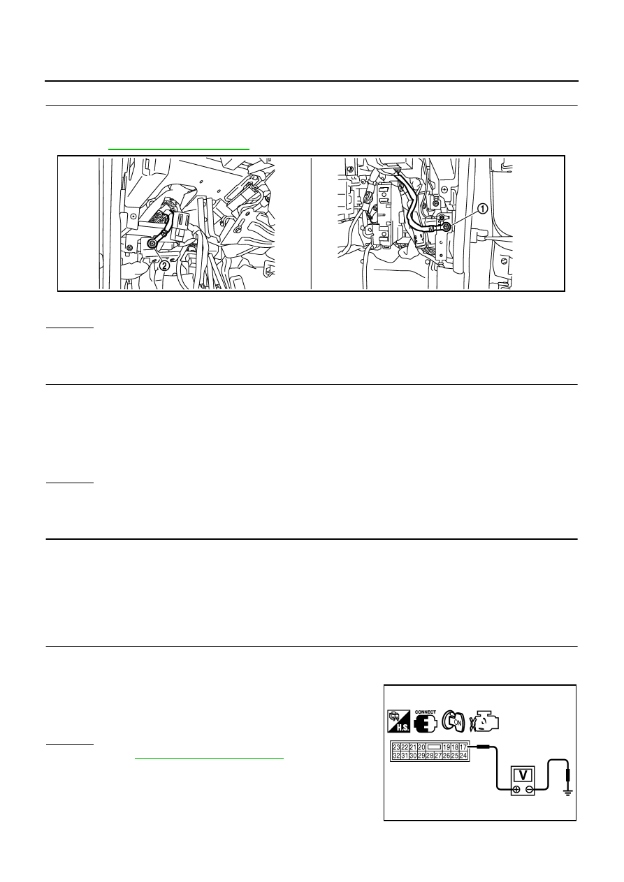
4.
CHECK GROUND CONNECTIONS
1.
Turn ignition switch OFF.
2.
Loosen and retighten ground screws on the body.
Refer to
OK or NG
OK
>> GO TO 5.
NG
>> Repair or replace ground connections.
5.
CHECK ECM GROUND CIRCUIT FOR OPEN AND SHORT-I
1.
Disconnect ECM harness connector.
2.
Check harness continuity between ECM terminals 1, 115, 116 and ground.
Refer to Wiring Diagram.
3.
Also check harness for short to power.
OK or NG
OK
>> GO TO 7.
NG
>> GO TO 6.
6.
DETECT MALFUNCTIONING PART
Check the following.
●
Harness connectors F102, M72
●
Harness for open or short between ECM and ground
>> Repair open circuit or short to power in harness or connectors.
7.
CHECK ECM POWER SUPPLY CIRCUIT-II
1.
Reconnect ECM harness connector.
2.
Turn ignition switch ON.
3.
Check voltage between IPDM E/R terminal 17 and ground with
CONSULT-II or tester.
OK or NG
OK
>> Go to
.
NG
>> GO TO 8.
1.
Body ground M70
2.
Body ground M16
PBIB2782E
Continuity should exist.
Voltage: Battery voltage
PBIB1915E
Нет комментариевНе стесняйтесь поделиться с нами вашим ценным мнением.
Текст