Infiniti M35/M45 Y50. Manual — part 239
POWER DOOR LOCK SYSTEM
BL-25
C
D
E
F
G
H
J
K
L
M
A
B
BL
System Description
NIS001WQ
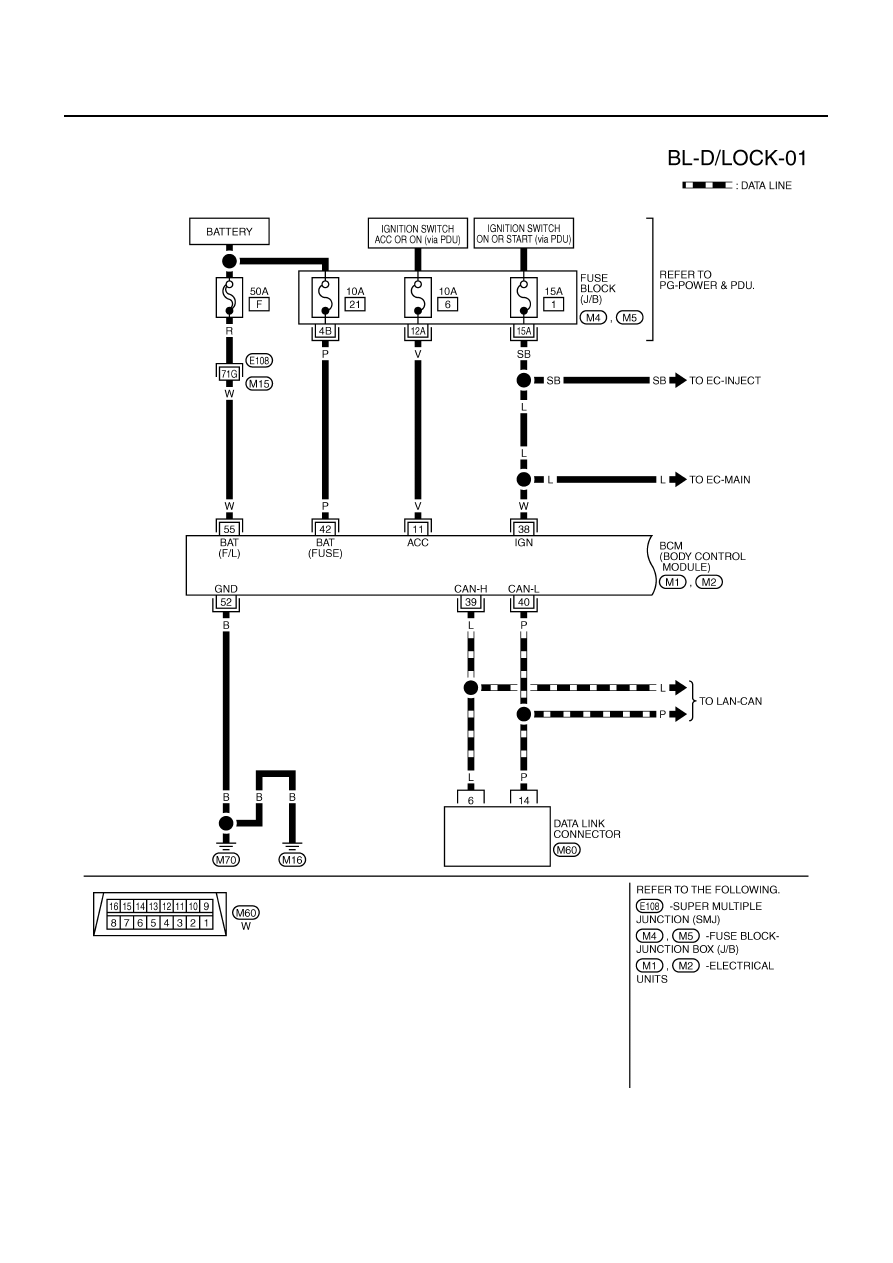
Power is supplied at all times
●
through 50A fusible link (letter F , located in the fuse and fusible link box).
●
to BCM terminal 55,
●
through 10A fuse [No. 21, located in the fuse block (J/B)]
●
to BCM terminal 42.
When ignition switch is in ACC or ON position, power is supplied
●
through 10A fuse [No. 6, located in fuse block (J/B)]
●
to BCM terminal 11.
When ignition switch is in ON or START position, power is supplied
●
through 15A fuse [No. 1, located in fuse block (J/B)]
●
to BCM terminal 38.
Ground is supplied
●
to BCM terminal 52
●
through body grounds M16 and M70.
When the door is locked or unlocked with power window main switch (door lock and unlock switch), ground is
supplied
●
to CPU of power window main switch
●
through power window main switch (door lock and unlock switch) terminal 17
●
through grounds M16 and M70.
Then power window main switch (door lock and unlock switch) operation signal is sent.
●
to BCM terminal 22
●
from power window main switch (door lock and unlock switch) terminal 14
When the door is locked or unlocked with power window sub-switch (front passenger side) (door lock and
unlock switch), ground is supplied
●
to CPU of power window sub-switch
●
through power window sub-switch (front passenger side) (door lock and unlock switch) terminal 11
●
through grounds M16 and M70.
Then power window sub-switch (front passenger side) (door lock and unlock switch) operation signal is sent
●
to BCM terminal 22
●
from power window sub-switch (front passenger side) (door lock and unlock switch) terminal 16.
When the door is locked with front door key cylinder switch (driver side), ground is supplied
●
to CPU of power window main switch
●
through power window main switch (door lock and unlock switch) terminal 4
●
through front door key cylinder switch (driver side) terminals 6 and 4
●
through grounds M16 and M70.
Then front door key cylinder switch (driver side) operation signal (lock) is sent
●
to BCM terminal 22
●
from power window main switch (door lock and unlock switch) terminal 14
When the door is unlocked with front door key cylinder switch (driver side), ground is supplied
●
to CPU of power window main switch
●
through power window main switch (door lock and unlock switch) terminal 6
●
through front door key cylinder switch (driver side) terminals 5 and 4
●
through grounds M16 and M70.
Then front door key cylinder switch (driver side) operation signal (unlock) is sent
●
to BCM terminal 22
●
from power window main switch (door lock and unlock switch) terminal 14
BCM is connected to power window main switch and power window sub-switch as serial link.
BL-26
POWER DOOR LOCK SYSTEM
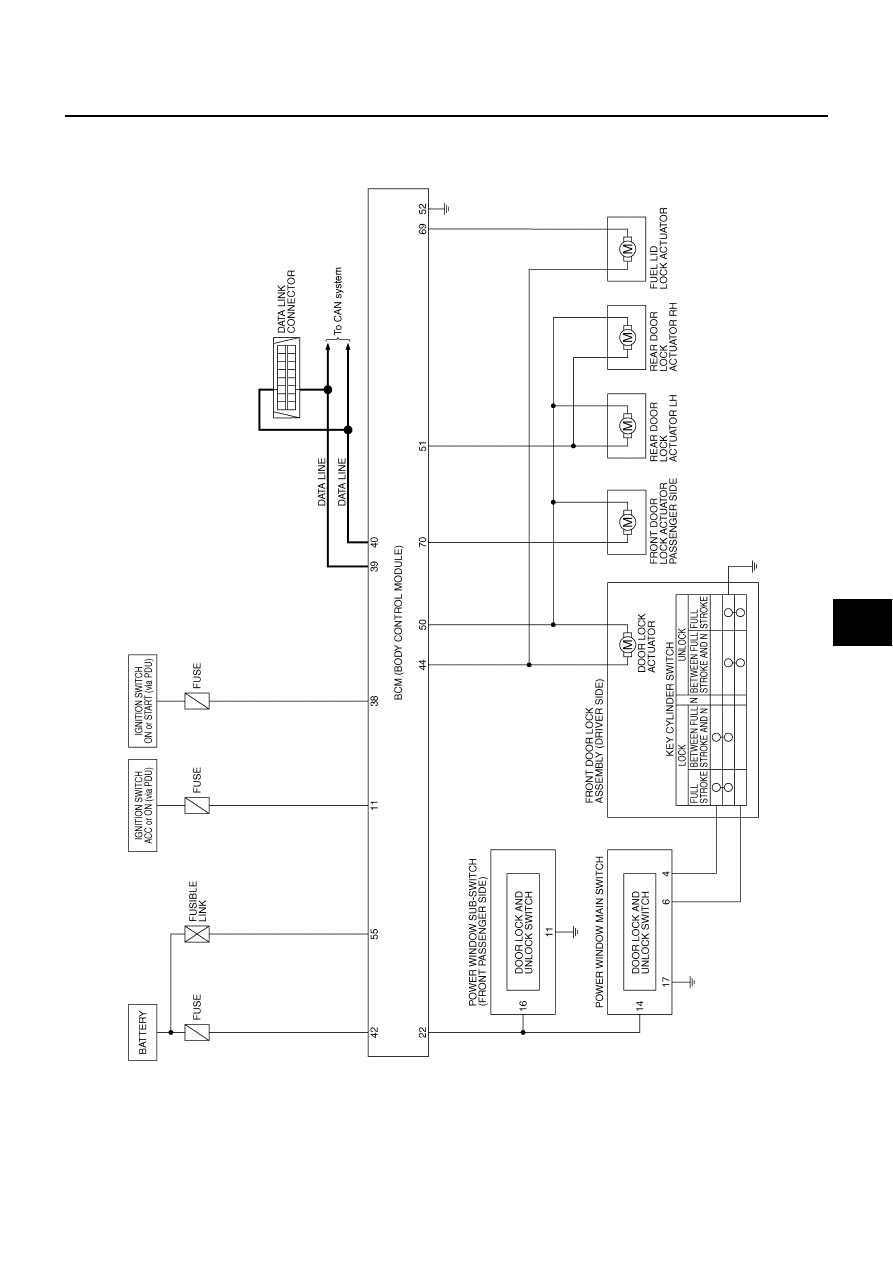
DOOR LOCK ACTUATOR OPERATION
When door is locked with door lock and unlock switch, all door lock actuator is locked. Ground is supplied
●
to BCM terminal 50
●
through each door lock actuator terminals 2 and 1
●
through BCM terminals 44 (driver side), 70 (passenger side) and 51 (rear door).
When door is unlocked with door lock and unlock switch, all door lock actuator is unlocked. Ground is supplied
●
to BCM terminals 44 (driver side), 70 (passenger side) and 51 (rear door)
●
through each door lock actuator terminals 1 and 2
●
through BCM terminal 50.
FUEL LID OPERATION
When door is locked with door lock and unlock switch, fuel lid lock actuator is locked. Ground is supplied
●
to BCM terminal 69
●
through fuel lid lock actuator terminals 2 and 1
●
through BCM terminal 44.
When door is unlocked with door lock and unlock switch, fuel lid lock actuator is unlocked. Ground is supplied
●
to BCM terminal 44
●
through fuel lid lock actuator terminals 1 and 2
●
through BCM terminal 69.
In this condition, fuel lid can be opened if it is pushed.
OUTLINE
Functions Available by Operating the Door Lock and Unlock Switches on Driver's Door and
Passenger's Door
●
Interlocked with the locking operation of door lock and unlock switch, door lock actuators of all doors and
fuel lid lock actuator are locked.
●
Interlocked with the unlocking operation of door lock and unlock switch, door lock actuators of all doors
and fuel lid lock actuator are unlocked.
Functions Available by Operating the Key Cylinder Switch on Driver's Door
●
Interlocked with the locking operation of door key cylinder, door lock actuators of all doors and fuel lid lock
actuator are locked.
Selective Unlock Operation
●
When door key cylinder is unlocked, door lock actuator driver side and fuel lid lock actuator are unlocked.
●
When door key cylinder is unlocked for the second time within 5 seconds after the first operation, door
lock actuators on all doors are unlocked.
Select unlock operation mode can be changed using “DOOR LOCK-UNLOCK SET” mode in “WORK SUP-
PORT”. Refer to
Key Reminder Door System
Refer to
BL-49, "Key Reminder Function"
.
CAN Communication System Description
NIS001WR
CAN (Controller Area Network) is a serial communication line for real time application. It is an on-vehicle mul-
tiplex communication line with high data communication speed and excellent error detection ability. Many elec-
tronic control units are equipped onto a vehicle, and each control unit shares information and links with other
control units during operation (not independent). In CAN communication, control units are connected with 2
communication lines (CAN H line, CAN L line) allowing a high rate of information transmission with less wiring.
Each control unit transmits/receives data but selectively reads required data only.
CAN Communication Unit
NIS001WS
Refer to
POWER DOOR LOCK SYSTEM
BL-27
C
D
E
F
G
H
J
K
L
M
A
B
BL
Schematic
NIS001WT
TIWT2016E
BL-28
POWER DOOR LOCK SYSTEM
Wiring Diagram —D/LOCK—
NIS001WU
TIWT1286E
Нет комментариевНе стесняйтесь поделиться с нами вашим ценным мнением.
Текст