Infiniti M35/M45 Y50. Manual — part 56
DTC P1752 INPUT CLUTCH SOLENOID VALVE
AT-147
D
E
F
G
H
I
J
K
L
M
A
B
AT
DTC P1752 INPUT CLUTCH SOLENOID VALVE
PFP:31940
Description
NCS001N5
Input clutch solenoid valve is controlled by the TCM in response to signals sent from the PNP switch, vehicle
speed sensor and accelerator pedal position sensor (throttle position sensor). Gears will then be shifted to the
optimum position.
CONSULT-II Reference Value
NCS001N6
On Board Diagnosis Logic
NCS001N7
●
This is an OBD-II self-diagnostic item.
●
Diagnostic trouble code “P1752 I/C SOLENOID/CIRC” with CONSULT-II or 5th judgement flicker without
CONSULT-II is detected under the following conditions.
–
When TCM detects an improper voltage drop when it tries to operate the solenoid valve.
–
When TCM detects as irregular by comparing target value with monitor value.
Possible Cause
NCS001N8
●
Harness or connectors
(Solenoid circuit is open or shorted.)
●
Input clutch solenoid valve
DTC Confirmation Procedure
NCS001N9
CAUTION:
Always drive vehicle at a safe speed.
NOTE:
If “DTC Confirmation Procedure” has been previously performed, always turn ignition switch OFF and
wait at least 10 seconds before performing the next test.
After the repair, perform the following procedure to confirm the malfunction is eliminated.
WITH CONSULT-II
1.
Turn ignition switch ON.
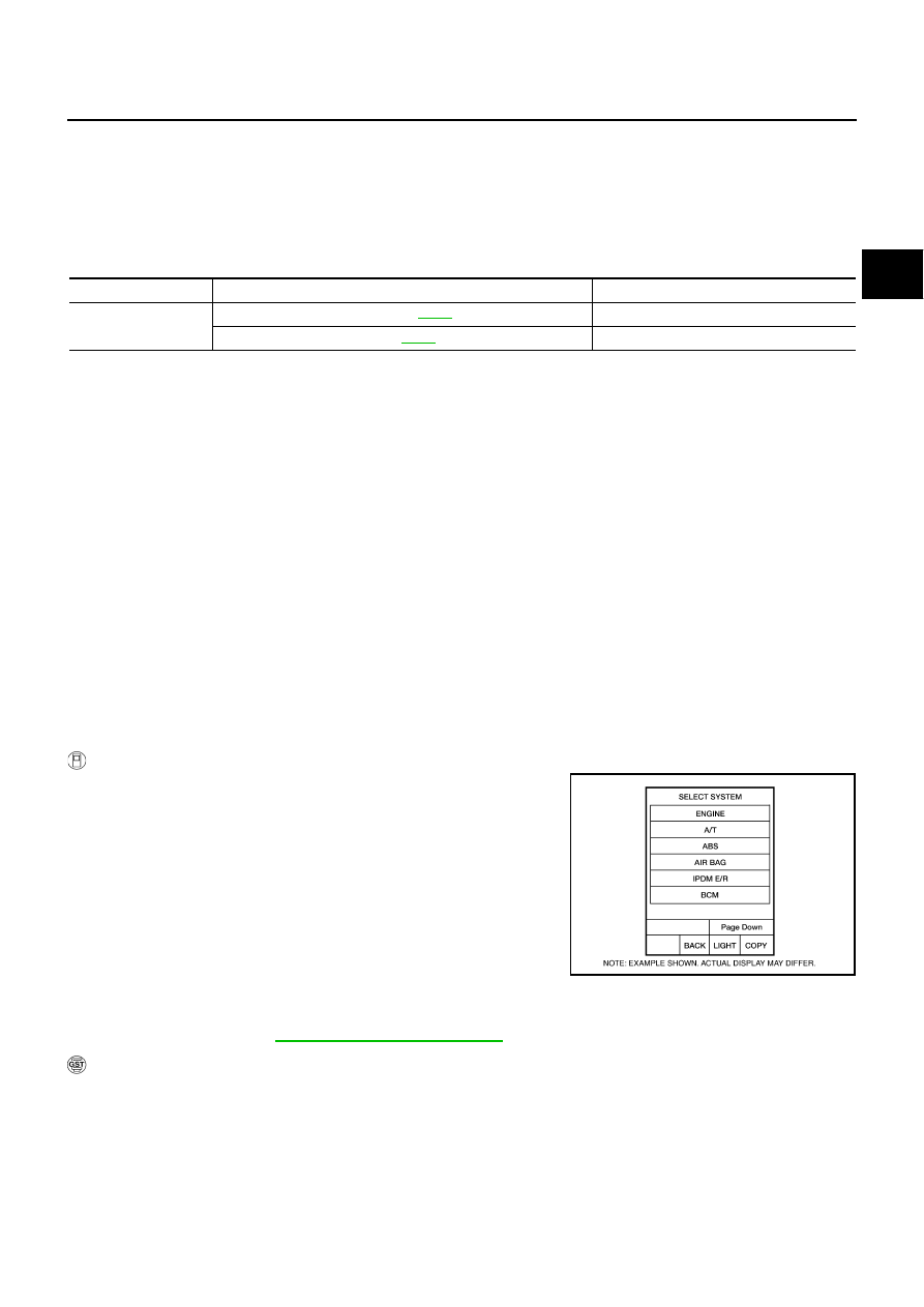
2.
Select “SELECTION FROM MENU” in “DATA MONITOR” mode
for “A/T” with CONSULT-II and check monitor “ACCELE POSI”,
“SLCT LVR POSI” and “GEAR”.
3.
Touch “START”.
4.
Start engine.
5.
Drive vehicle and maintain the following conditions for at least 5
consecutive seconds.
ACCELE POSI: 1.5/8 - 2.0/8
SLCT LVR POSI: “D” position
GEAR: “3”
Þ
“4” (I/C ON/OFF)
Driving location: Driving the vehicle uphill (increased engine load) will help maintain the driving
conditions required for this test.
6.
If DTC is detected go to
AT-148, "Diagnostic Procedure"
WITH GST
Follow the procedure “WITH CONSULT-II”.
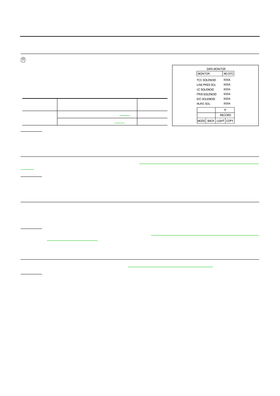
Item name
Condition
Display value (Approx.)
I/C SOLENOID
Input clutch disengaged. Refer to
.
0.6 - 0.8 A
Input clutch engaged. Refer to
0 - 0.05 A
BCIA0030E
AT-148
DTC P1752 INPUT CLUTCH SOLENOID VALVE
Diagnostic Procedure
NCS001NA
1.
CHECK INPUT SIGNAL
With CONSULT-II
1.
Turn ignition switch ON.
2.
Select “MAIN SIGNALS” in “DATA MONITOR” mode for “A/T”
with CONSULT-II.
3.
Start engine.
4.
Read out the value of “I/C SOLENOID” while driving.
OK or NG
OK
>> GO TO 4.
NG
>> GO TO 2.
2.
CHECK TCM POWER SUPPLY AND GROUND CIRCUIT
Check TCM power supply and ground circuit. Refer to
AT-180, "MAIN POWER SUPPLY AND GROUND CIR-
OK or NG
OK
>> GO TO 3.
NG
>> Repair or replace damaged parts.
3.
DETECT MALFUNCTIONING ITEM
Check the following.
●
The A/T assembly harness connector pin terminals for damage or loose connection with harness connec-
tor.
OK or NG
OK
>> Replace the control valve with TCM. Refer to
AT-236, "Control Valve With TCM and A/T Fluid
NG
>> Repair or replace damaged parts.
4.
CHECK DTC
Perform “DTC Confirmation Procedure”. Refer to
AT-147, "DTC Confirmation Procedure"
OK or NG
OK
>> INSPECTION END
NG
>> GO TO 2.
Item name
Condition
Display value
(Approx.)
I/C SOLENOID
Input clutch disengaged. Refer to
0.6 - 0.8 A
Input clutch engaged. Refer to
0 - 0.05 A
SCIA4793E
DTC P1754 INPUT CLUTCH SOLENOID VALVE FUNCTION
AT-149
D
E
F
G
H
I
J
K
L
M
A
B
AT
DTC P1754 INPUT CLUTCH SOLENOID VALVE FUNCTION
PFP:31940
Description
NCS001NB
●
Input clutch solenoid valve is controlled by the TCM in response to signals sent from the PNP switch, vehi-
cle speed sensor and accelerator pedal position sensor (throttle position sensor). Gears will then be
shifted to the optimum position.
●
This is not only caused by electrical malfunction (circuits open or shorted) but also by mechanical mal-
function such as control valve sticking, improper solenoid valve operation.
CONSULT-II Reference Value
NCS001NC
On Board Diagnosis Logic
NCS001ND
●
This is an OBD-II self-diagnostic item.
●
Diagnostic trouble code “P1754 I/C SOLENOID FNCTN” with CONSULT-II or 5th judgement flicker with-
out CONSULT-II is detected under the following conditions.
–
When TCM detects that actual gear ratio is irregular, and relation between gear position and condition of
ATF pressure switch 3 is irregular during depressing accelerator pedal. (Other than during shift change.)
–
When TCM detects that relation between gear position and condition of ATF pressure switch 3 is irregular
during releasing accelerator pedal. (Other than during shift change.)
Possible Cause
NCS001NE
●
Harness or connectors
(Solenoid and switch circuits are open or shorted.)
●
Input clutch solenoid valve
●
ATF pressure switch 3
DTC Confirmation Procedure
NCS001NF
CAUTION:
Always drive vehicle at a safe speed.
NOTE:
If “DTC Confirmation Procedure” has been previously performed, always turn ignition switch OFF and
wait at least 10 seconds before performing the next test.
After the repair, perform the following procedure to confirm the malfunction is eliminated.
WITH CONSULT-II
1.
Start engine.
2.
Accelerate vehicle to maintain the following conditions.
ACCELE POSI: 1.5/8 - 2.0/8
SLCT LVR POSI: “D” position
GEAR: “3”
Þ
“4” (I/C ON/OFF)
Driving location: Driving the vehicle uphill (increased
engine load) will help maintain the driving conditions
required for this test.
3.
Perform step 2 again.
4.
Turn ignition switch OFF, then perform step 1 to 3 again.
5.
Check “SELF-DIAG RESULTS” mode for “A/T” with CONSULT-
II. If DTC (P1754) is detected, go to
AT-150, "Diagnostic Procedure"
If DTC (P1752) is detected, go to
AT-148, "Diagnostic Procedure"
If DTC (P1843) is detected, go to
AT-175, "Diagnostic Procedure"
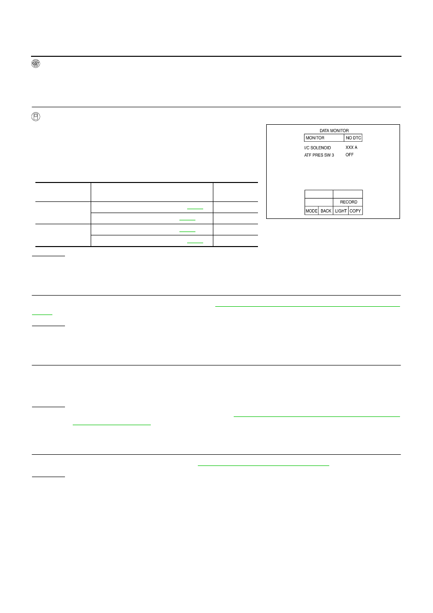
Item name
Condition
Display value (Approx.)
I/C SOLENOID
Input clutch disengaged. Refer to
.
0.6 - 0.8 A
Input clutch engaged. Refer to
0 - 0.05 A
ATF PRES SW 3
Input clutch engaged. Refer to
.
ON
Input clutch disengaged. Refer to
.
OFF
BCIA0030E
AT-150
DTC P1754 INPUT CLUTCH SOLENOID VALVE FUNCTION
WITH GST
Follow the procedure “WITH CONSULT-II”.
Diagnostic Procedure
NCS001NG
1.
CHECK INPUT SIGNALS
With CONSULT-II
1.
Start engine.
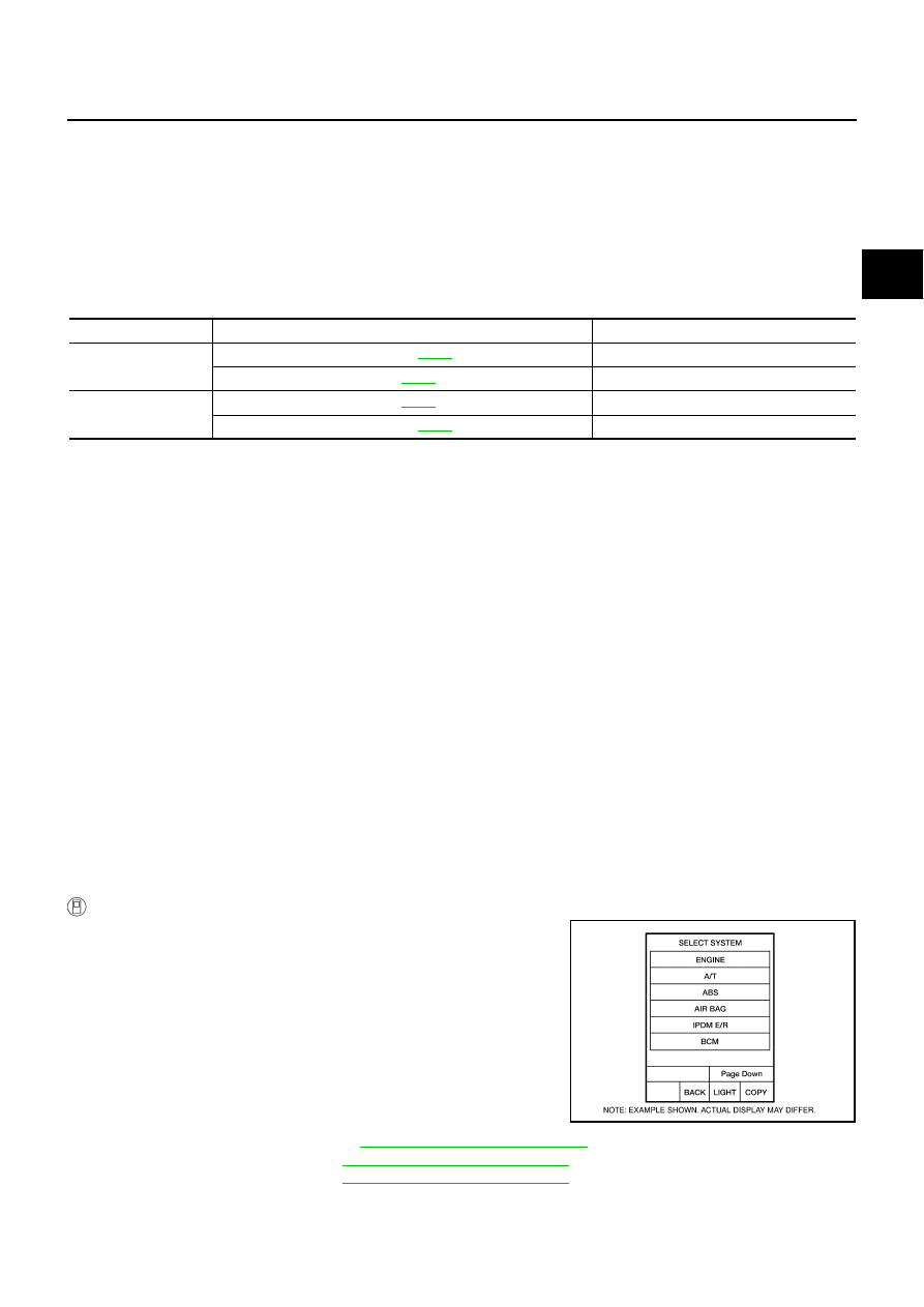
2.
Select “SELECTION FROM MENU” in “DATA MONITOR” mode
for “A/T” with CONSULT-II.
3.
Drive vehicle in “D” position (3rd
Þ
4th gear), and confirm the
ON/OFF actuation of “ATF PRES SW 3” and electrical current
value of “I/C SOLENOID”.
OK or NG
OK
>> GO TO 4.
NG
>> GO TO 2.
2.
CHECK TCM POWER SUPPLY AND GROUND CIRCUIT
Check TCM power supply and ground circuit. Refer to
AT-180, "MAIN POWER SUPPLY AND GROUND CIR-
OK or NG
OK
>> GO TO 3.
NG
>> Repair or replace damaged parts.
3.
DETECT MALFUNCTIONING ITEM
Check the following.
●
The A/T assembly harness connector pin terminals for damage or loose connection with harness connec-
tor.
OK or NG
OK
>> Replace the control valve with TCM. Refer to
AT-236, "Control Valve With TCM and A/T Fluid
NG
>> Repair or replace damaged parts.
4.
CHECK DTC
Perform “DTC Confirmation Procedure”. Refer to
AT-149, "DTC Confirmation Procedure"
OK or NG
OK
>> INSPECTION END
NG
>> GO TO 2.
Item name
Condition
Display value
(Approx.)
I/C SOLENOID
Input clutch disengaged. Refer to
.
0.6 - 0.8 A
Input clutch engaged. Refer to
0 - 0.05 A
ATF PRES SW 3
Input clutch engaged. Refer to
.
ON
Input clutch disengaged. Refer to
.
OFF
SCIA4795E
Нет комментариевНе стесняйтесь поделиться с нами вашим ценным мнением.
Текст