Infiniti M35/M45 Y50. Manual — part 424
DTC P0011, P0021 IVT CONTROL
EC-169
[VQ35DE]
C
D
E
F
G
H
I
J
K
L
M
A
EC
6.
CHECK TIMING CHAIN INSTALLATION
Check service records for any recent repairs that may cause timing chain misaligned.
Yes or No
Yes
>> Check timing chain installation. Refer to
.
No
>> GO TO 7.
7.
CHECK LUBRICATION CIRCUIT
Refer to
EM-93, "Inspection of Camshaft Sprocket (INT) Oil Groove"
.
OK or NG
OK
>> GO TO 8.
NG
>> Clean lubrication line.
8.
CHECK INTERMITTENT INCIDENT
Refer to
EC-153, "TROUBLE DIAGNOSIS FOR INTERMITTENT INCIDENT"
for CKP sensor (POS) and
>> INSPECTION END
Component Inspection
NBS004TY
INTAKE VALVE TIMING CONTROL SOLENOID VALVE
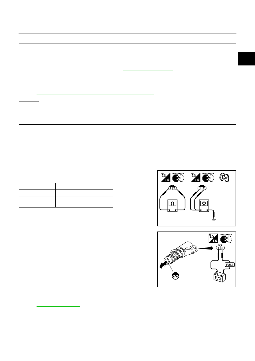
1.
Disconnect intake valve timing control solenoid valve harness connector.
2.
Check resistance between intake valve timing control solenoid
valve terminals as follows.
If NG, replace intake valve timing control solenoid valve.
If OK, go to next step.
3.
Remove intake valve timing control solenoid valve.
4.
Provide 12V DC between intake valve timing control solenoid
valve terminals and then interrupt it. Make sure that the plunger
moves as shown in the figure.
CAUTION:
Do not apply 12V DC continuously for 5 seconds or more.
Doing so may result in damage to the coil in intake valve
timing control solenoid valve.
If NG, replace intake valve timing control solenoid valve.
NOTE:
Always replace O-ring when intake valve timing control
solenoid valve is removed.
Removal and Installation
NBS004TZ
INTAKE VALVE TIMING CONTROL SOLENOID VALVE
Refer to
Are there any service records that may cause timing chain misaligned?
Terminals
Resistance
1 and 2
7.0 - 7.5
Ω
[at 20
°
C (68
°
F)]
1 or 2 and ground
∞Ω
(Continuity should not exist)
PBIB0193E
PBIB2275E
EC-170
[VQ35DE]
DTC P0031, P0032, P0051, P0052 A/F SENSOR 1 HEATER
DTC P0031, P0032, P0051, P0052 A/F SENSOR 1 HEATER
PFP:22693
Description
NBS004U0
SYSTEM DESCRIPTION
The ECM performs ON/OFF duty control of the A/F sensor 1 heater corresponding to the engine operating
condition to keep the temperature of A/F sensor 1 element at the specified range.
CONSULT-II Reference Value in Data Monitor Mode
NBS004U1
Specification data are reference values.
On Board Diagnosis Logic
NBS004U2
DTC Confirmation Procedure
NBS004U3
NOTE:
If DTC Confirmation Procedure has been previously conducted, always turn ignition switch OFF and wait at
least 10 seconds before conducting the next test.
TESTING CONDITION:
Before performing the following procedure, confirm that battery voltage is between 10.5V and 16V at
idle.
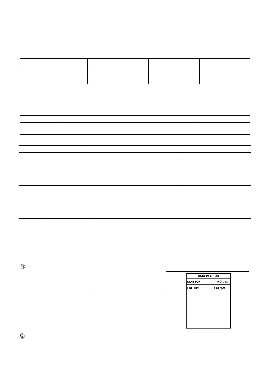
WITH CONSULT-II
1.
Turn ignition switch ON and select “DATA MONITOR” mode with
CONSULT-II.
2.
Start engine and let it idle for at least 10 seconds.
3.
If 1st trip DTC is detected, go to
EC-174, "Diagnostic Procedure"
.
WITH GST
Follow the procedure “WITH CONSULT-II” above.
Sensor
Input Signal to ECM
ECM function
Actuator
Camshaft position sensor (PHASE)
Crankshaft position sensor (POS)
Engine speed
Air fuel ratio (A/F) sensor 1
heater control
Air fuel ratio (A/F) sensor 1
heater
Mass air flow sensor
Amount of intake air
MONITOR ITEM
CONDITION
SPECIFICATION
A/F S1 HTR (B1)
A/F S1 HTR (B2)
●
Engine: After warming up, idle the engine
0 - 100%
DTC No.
Trouble diagnosis name
DTC detecting condition
Possible cause
P0031
0031
(Bank 1)
Air fuel ratio (A/F) sensor
1 heater control circuit
low
The current amperage in the A/F sensor 1 heater
circuit is out of the normal range.
(An excessively low voltage signal is sent to ECM
through the A/F sensor 1 heater.)
●
Harness or connectors
(The A/F sensor 1 heater circuit is
open or shorted.)
●
A/F sensor 1 heater
P0051
0051
(Bank 2)
P0032
0032
(Bank 1)
Air fuel ratio (A/F) sensor
1 heater control circuit
high
The current amperage in the A/F sensor 1 heater
circuit is out of the normal range.
(An excessively high voltage signal is sent to ECM
through the A/F sensor 1 heater.)
●
Harness or connectors
(The A/F sensor 1 heater circuit is
shorted.)
●
A/F sensor 1 heater
P0052
0052
(Bank 2)
SEF058Y
DTC P0031, P0032, P0051, P0052 A/F SENSOR 1 HEATER
EC-171
[VQ35DE]
C
D
E
F
G
H
I
J
K
L
M
A
EC
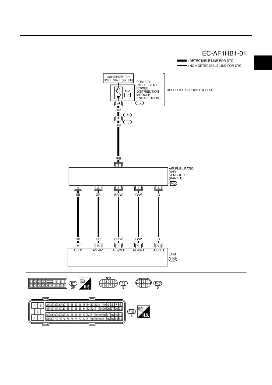
Wiring Diagram
NBS004U4
BANK 1
TBWT0968E
EC-172
[VQ35DE]
DTC P0031, P0032, P0051, P0052 A/F SENSOR 1 HEATER
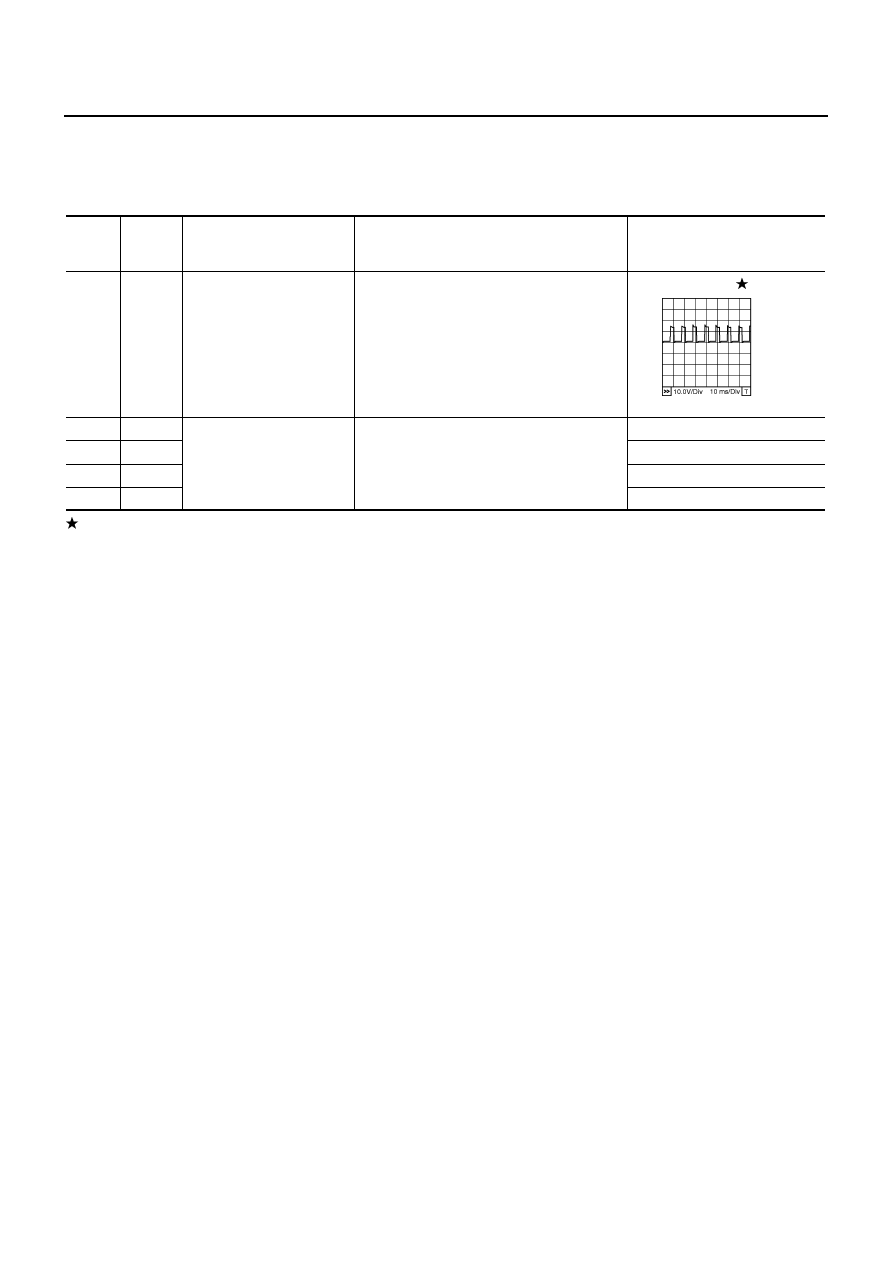
Specification data are reference values and are measured between each terminal and ground.
Pulse signal is measured by CONSULT-II.
CAUTION:
Do not use ECM ground terminals when measuring input/output voltage. Doing so may result in dam-
age to the ECM's transistor. Use a ground other than ECM terminals, such as the ground.
: Average voltage for pulse signal (Actual pulse signal can be confirmed by oscilloscope.)
TER-
MINAL
NO.
WIRE
COLOR
ITEM
CONDITION
DATA (DC Voltage)
2
SB
A/F sensor 1 heater
(bank 1)
[Engine is running]
●
Warm-up condition
●
Idle speed
Approximately 5V
16
G/W
A/F sensor 1 (bank 1)
[Engine is running]
●
Warm-up condition
●
Idle speed
Approximately 3.1V
35
BR/W
Approximately 2.6V
56
G
Approximately 2.3V
75
GR
Approximately 2.3V
PBIB1584E
Нет комментариевНе стесняйтесь поделиться с нами вашим ценным мнением.
Текст