Infiniti M35/M45 Y50. Manual — part 1117
TROUBLE DIAGNOSIS
STC-25
[RAS]
C
D
E
F
H
I
J
K
L
M
A
B
STC
TGWT0066E
STC-26
[RAS]
TROUBLE DIAGNOSIS
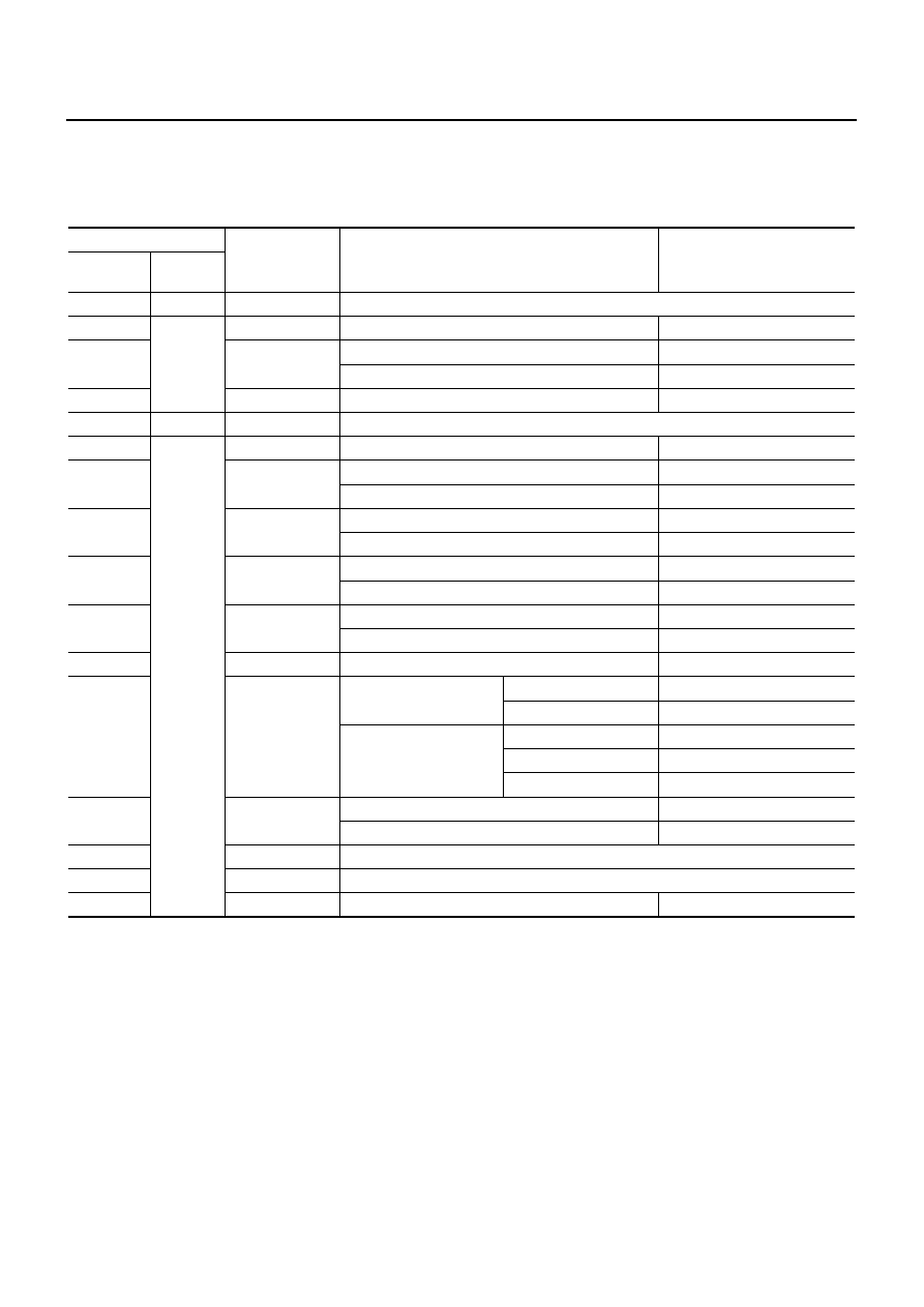
Control Unit Input/Output Signal Standard
NGS000EF
CIRCUIT TESTER REFERENCE VALUE
CAUTION:
When checked using a circuit tester for voltage measurement, connector terminals should not be
forcefully extended.
Terminal
Measuring point
Measuring condition
Standard
+
(wire color)
–
1 (L)
—
CAN-H
—
4 (G)
Ground
RR MAIN SIG
Neutral
Approx. 2.4 V
5 (W)
RR VCC
Ignition switch ON
Approx. 5 V
Ignition switch OFF
Approx. 0 V
7 (R)
RR SUB SIG
Neutral
Approx. 2.4 V
8 (P)
—
CAN-L
—
15 (B/W)
Ground
RR SEN GND
—
Continuity exit
22 (P/L)
STOP/L SW
Brake pedal depressed
Battery voltage (Approx. 12 V)
Brake pedal not depressed
Approx. 0 V
25 (L/W)
RLY
Ignition switch ON
Battery voltage (Approx. 12 V)
Ignition switch OFF
Approx. 0 V
26 (G/W)
WARN
ON
Approx. 1.4 V or less
OFF
Ignition voltage: 2.8 V or more
27 (G/B)
IGN
Ignition switch ON
Battery voltage (Approx. 12 V)
Ignition switch OFF
Approx. 0 V
34 (B)
GND
—
Continuity exit
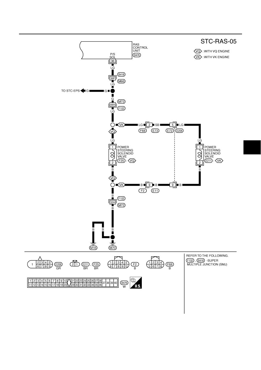
36 (LG)
P/S SOL
Normal (Vehicle speed)
0 km/h (0 MPH)
Approx. 4.4 - 6.6 V
100 km/h (62 MPH)
Approx. 2.4 - 3.6 V
In fail-safe mode
(Engine speed)
0 - 1,500 rpm
Approx. 4.4 - 6.6 V
1,500 - 3,000 rpm
Approx. 3.5 V
3,000 rpm or more
Approx. 2.1 V
37 (L/Y)
MOTOR VCC
Ignition switch ON
Battery voltage (Approx. 12 V)
Ignition switch OFF
Approx. 0 V
38 (W)
MTR-1 (RH)
—
39 (B)
MTR-2 (LH)
—
40 (B/W)
MOTOR GND
—
Continuity exit
TROUBLE DIAGNOSIS
STC-27
[RAS]
C
D
E
F
H
I
J
K
L
M
A
B
STC
STANDARD BY CONSULT-II
CAUTION:
The output signal indicates the RAS control unit calculation data. The normal values will be displayed
even in the event that the output circuit (harness) is open.
CONSULT-II Function (RAS/HICAS)
NGS000EG
FUNCTION
CONSULT-II can display each self-diagnostic item using the diagnostic test modes shown following.
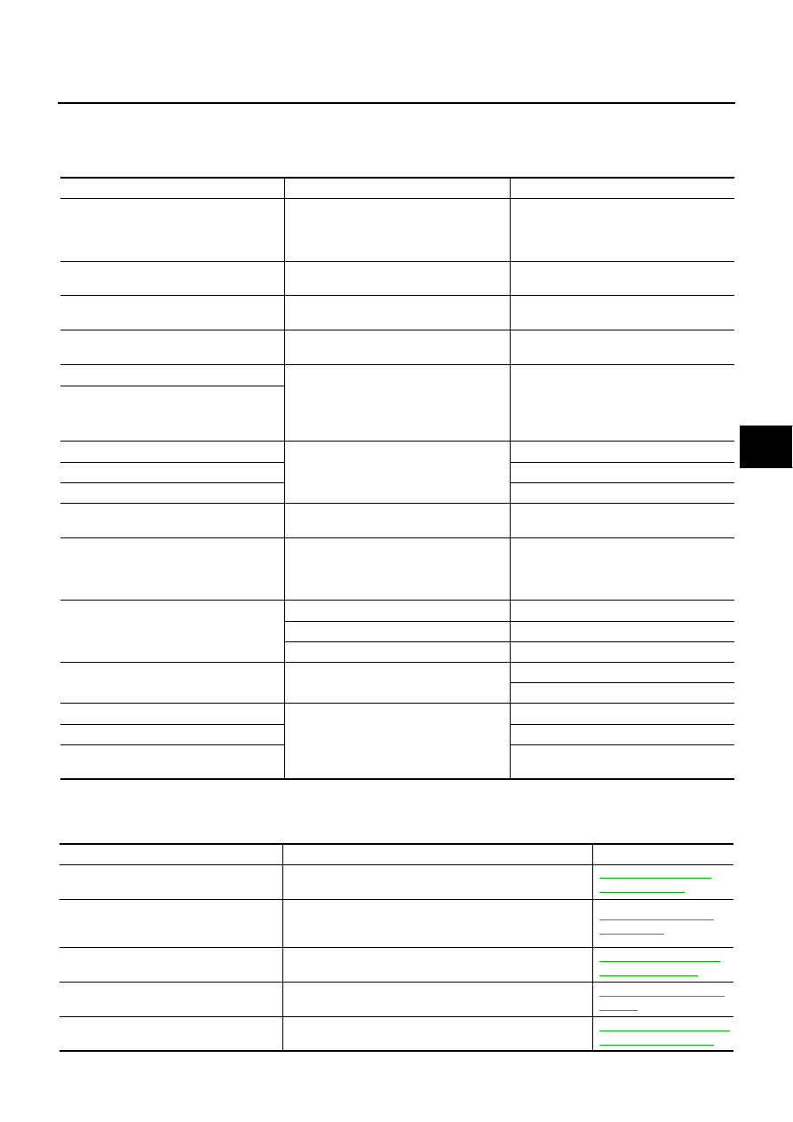
Monitor item
Condition
Reference values
VHCL SPEED SE [km/h] or [mph]
Ignition switch ON or engine running
Almost in accordance with the speedome-
ter display. It is not a malfunction, through
it might not be corresponding just after
ignition switch is turned ON.
STEERING ANG [
°
]
Turning steering wheel clockwise or coun-
terclockwise.
Displays the angle when the steering
wheel turns from the neutral position
ENGINE SPEED [rpm]
Engine running
Almost in accordance with tachometer dis-
play
POWER STR SOL [A]
Accelerate the vehicle from 0 to 100 km/h
(0 to 62 MPH)
0 km/h (0 MPH): Approx. 1.10 A
100 km/h (62 MPH): Approx. 0.54 A
RR ST ANG-MAI [V]
Perform the ACTIVE TEST and stroke the
actuator (with tires off the ground)
Neutral: Approx. 2.4 V
Turn steering wheel to right for full stroke:
Approx. 4.4 V
Turn steering wheel to left for full stroke:
Approx. 0.4 V
RR ST ANG-SUB [V]
RR ST ANG-VOL [V]
Ignition switch ON or engine running
Approx. 5 V
C/U VOLTAGE [V]
Battery voltage (Approx. 12 V)
MOTOR VOLTAGE [V]
Battery voltage (Approx. 12V)
MOTOR CURRENT [A]
Perform the ACTIVE TEST and stroke the
actuator.
It is normal when there is the current out-
put at stroke
MTR CRNT OPE [A]
Turning steering wheel clockwise or coun-
terclockwise while ignition switch is ON or
running the engine
Neutral (Steering force is zero and straight-
ahead position): Approx. 0 A
The value is changed according to steering
left or right
RR ANGLE OPE [
°
]
RAS actuator assembly turned full right
Approx. 1
°
RAS actuator assembly neutral
Approx. 0
°
RAS actuator assembly turned full left
Approx. - 1
°
STOP LAMP SW [ON/OFF]
Depressing or releasing brake pedal
Brake pedal depressed: ON
Brake pedal not depressed: OFF
HICAS RELAY [ON/OFF]
Ignition switch ON or engine running
Ignition switch ON: ON
FAIL SAFE [ON/OFF]
Not activated
WARNING LAMP (ON/OFF)
RAS warning lamp ON: ON
RAS warning lamp OFF: OFF
Diagnostic test mode
Function
Reference page
SELF-DIAG RESULTS
Receives self-diagnosis results from RAS control unit and
indicates DTCs.
STC-28, "SELF-DIAG
RESULT MODE"
DATA MONITOR
Receives input/output signals from RAS control unit and
indicates and stores them to facilitate locating cause of mal-
functions.
CAN DIAG SUPPORT MNTR
Monitors transmitting/receiving status of CAN communica-
tion.
LAN-44, "CAN Diagnos-
tic Support Monitor"
ACTIVE TEST
Sends command to RAS actuator to change output signals
and check operation of output system.
ECU PART NUMBER
Displays RAS control unit part number.
STC-28
[RAS]
TROUBLE DIAGNOSIS
CONSULT-II SETTING PROCEDURE
Refer to
GI-38, "CONSULT-II Start Procedure"
SELF-DIAG RESULT MODE
Operation Procedure
1.
Perform “CONSULT-II Start Procedure”. Refer to
GI-38, "CONSULT-II Start Procedure"
2.
Touch “PRINT” to print out the self-diagnostic results if necessary. Check RAS warning lamp if “NO FAIL-
URE” is displayed.
3.
Perform the appropriate inspection from the display item list, and repair or replace the malfunctioning
component. Refer to
Display Item List
CAUTION:
When malfunctions are detected in several systems, including the “CAN COMM [U1000]” and “CON-
TROL UNIT (CAN) [U1010]”, inspect the CAN communication system.
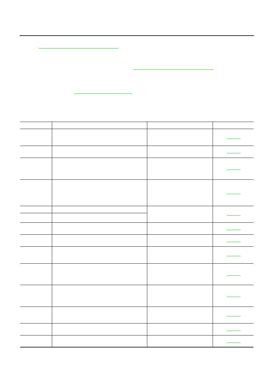
DTC
Diagnostic item
Diagnostic item is detected when...
Check items
C1923
STEERING ANGLE SEN [NO CHANGE]
While driving at 60 km/h (37 MPH)
or more, steering angle does not
change for a while.
C1924
STEERING ANGLE SEN [NO NEUT STATE]
When driving some distance, no
neutral signal (ON signal) is input.
C1915
RR ST ANGLE SENSOR [MAIN SIGNAL]
The main sensor input signal is
malfunctioning for some time
against the sensor power supply
value.
C1916
RR ST ANGLE SENSOR [SUB SIGNAL]
When the main sensor input signal
is 2.4 - 2.6 V, the sub sensor input
signal is malfunctioning for some
time compared to the sensor power
supply value.
C1917
RR ST ANGLE SENSOR [OFFSET SIG1]
An excessive difference has
occurred in the input values of main
sensor and sub sensor.
C1918
RR ST ANGLE SENSOR [OFFSET SIG2]
C1914
RR ST ANGLE SENSOR [ABNORMAL VOL]
Higher or lower value compared to
the standard voltage.
C1921
MOTOR OUTPUT
No engine speed is input for a cer-
tain time.
C1911
MOTOR VOLTAGE [LOW VOLTAGE]
The motor power supply voltage is
lower than ignition power supply
voltage with RAS motor relay ON.
C1912
MOTOR VOLTAGE [BAD OBSTRCT]
The motor power supply voltage is
inputting for some time with motor
power supply OFF by RAS control
unit.
C1913
MOTOR OUTPUT [ABNORMAL SIG]
When the motor current value is 10
A or more, actual output is exces-
sively low and the condition contin-
ues for some time.
C1902
MOTOR OUTPUT [REV CURRENT]
The current flows in the opposite
direction when the motor current is
output.
C1903
MOTOR OUTPUT [NO CURRENT]
The current flows when the motor
current is not output.
C1904
MOTOR OUTPUT [OVERCURRENT]
The excessive high current flows
when the motor current is output.
Нет комментариевНе стесняйтесь поделиться с нами вашим ценным мнением.
Текст