Infiniti M35/M45 Y50. Manual — part 498
DTC P0461 FUEL LEVEL SENSOR
EC-465
[VQ35DE]
C
D
E
F
G
H
I
J
K
L
M
A
EC
6.
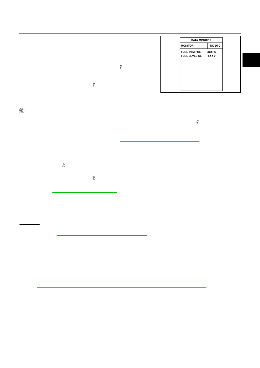
Select “FUEL LEVEL SE” in “DATA MONITOR” mode with CON-
SULT-II.
7.
Check “FUEL LEVEL SE” output voltage and note it.
8.
Select “FUEL PUMP” in “ACTIVE TEST” mode with CONSULT-
II.
9.
Touch “ON” and drain fuel approximately 30 (7-7/8 US gal, 6-
5/8 Imp gal) and stop it.
10. Check “FUEL LEVEL SE” output voltage and note it.
11. Fill fuel into the fuel tank for 30 (7-7/8 US gal, 6-5/8 Imp gal).
12. Check “FUEL LEVEL SE” output voltage and note it.
13. Confirm whether the voltage changes more than 0.03V during step 7 to 10 and 10 to 12.
EC-465, "Diagnostic Procedure"
WITH GST
NOTE:
Start from step 8, if it is possible to confirm that the fuel cannot be drained by 30 (7-7/8 US gal, 6-5/8
Imp gal) in advance.
1.
Prepare a fuel container and a spare hose.
2.
Release fuel pressure from fuel line. Refer to
EC-88, "FUEL PRESSURE RELEASE"
3.
Remove the fuel feed hose on the fuel level sensor unit.
4.
Connect a spare fuel hose where the fuel feed hose was removed.
5.
Turn ignition switch ON.
6.
Drain fuel by 30 (7-7/8 US gal, 6-5/8 Imp gal) from the fuel tank using proper equipment.
7.
Confirm that the fuel gauge indication varies.
8.
Fill fuel into the fuel tank for 30 (7-7/8 US gal, 6-5/8 Imp gal).
9.
Confirm that the fuel gauge indication varies.
EC-465, "Diagnostic Procedure"
Diagnostic Procedure
NBS0051H
1.
CHECK DTC WITH “UNIFIED METER AND A/C AMP.”
Refer to
OK or NG
OK
>> GO TO 2.
NG
DI-22, "Fuel Level Sensor Signal Inspection"
.
2.
CHECK INTERMITTENT INCIDENT
Refer to
EC-153, "TROUBLE DIAGNOSIS FOR INTERMITTENT INCIDENT"
>> INSPECTION END
Removal and Installation
NBS0051I
FUEL LEVEL SENSOR
Refer to
FL-4, "FUEL LEVEL SENSOR UNIT, FUEL FILTER AND FUEL PUMP ASSEMBLY"
SEF195Y
EC-466
[VQ35DE]
DTC P0462, P0463 FUEL LEVEL SENSOR CIRCUIT
DTC P0462, P0463 FUEL LEVEL SENSOR CIRCUIT
PFP:25060
Component Description
NBS0051J
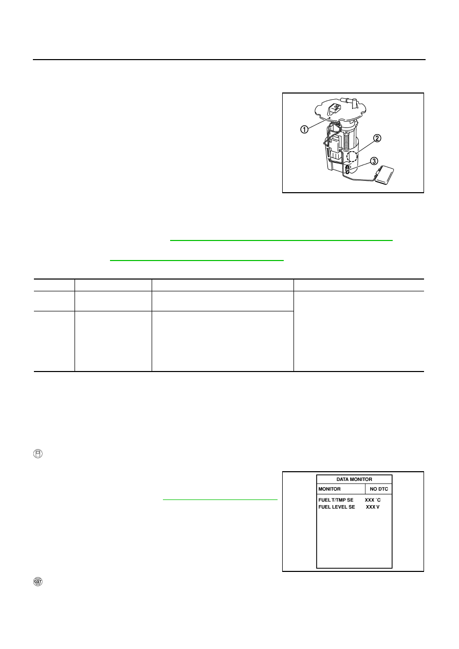
The fuel level sensor is mounted in the fuel level sensor unit.
The sensor detects a fuel level in the fuel tank and transmits a signal
to the “unified meter and A/C amp.”. The “unified meter and A/C
amp.” sends the fuel level sensor signal to the ECM through CAN
communication line.
It consists of two parts, one is mechanical float and the other is vari-
able resistor. Fuel level sensor output voltage changes depending on
the movement of the fuel mechanical float.
●
Fuel level sensor unit and fuel pump (1)
●
Fuel pressure regulator (2)
●
Fuel tank temperature sensor (3)
On Board Diagnosis Logic
NBS0051K
NOTE:
●
If DTC P0462 or P0463 is displayed with DTC U1000 or U1001, first perform the trouble diagnosis
for DTC U1000, U1001. Refer to
EC-161, "DTC U1000, U1001 CAN COMMUNICATION LINE"
.
●
If DTC P0462 or P0463 is displayed with DTC U1010, first perform the trouble diagnosis for DTC
U1010. Refer to
EC-164, "DTC U1010 CAN COMMUNICATION"
.
This diagnosis indicates the former, to detect open or short circuit malfunction.
DTC Confirmation Procedure
NBS0051L
NOTE:
If DTC Confirmation Procedure has been previously conducted, always turn ignition switch OFF and wait at
least 10 seconds before conducting the next test.
TESTING CONDITION:
Before performing the following procedure, confirm that battery voltage is more than 11V at ignition
switch ON.
WITH CONSULT-II
1.
Turn ignition switch ON.
2.
Select “DATA MONITOR” mode with CONSULT-II.
3.
Wait at least 5 seconds.
4.
If 1st trip DTC is detected, go to
EC-467, "Diagnostic Procedure"
.
WITH GST
Follow the procedure “WITH CONSULT-II” above.
PBIB2707E
DTC No.
Trouble diagnosis name
DTC detecting condition
Possible cause
P0462
0462
Fuel level sensor circuit
low input
An excessively low voltage from the sensor is
sent to ECM.
●
Harness or connectors
(The CAN communication line is open or
shorted)
●
Harness or connectors
(The sensor circuit is open or shorted)
●
Unified meter and A/C amp.
●
Fuel level sensor
P0463
0463
Fuel level sensor circuit
high input
An excessively high voltage from the sensor is
sent to ECM.
SEF195Y

DTC P0462, P0463 FUEL LEVEL SENSOR CIRCUIT
EC-467
[VQ35DE]
C
D
E
F
G
H
I
J
K
L
M
A
EC
Diagnostic Procedure
NBS0051M
1.
CHECK DTC WITH “UNIFIED METER AND A/C AMP.”
Refer to
OK or NG
OK
>> GO TO 2.
NG
DI-22, "Fuel Level Sensor Signal Inspection"
.
2.
CHECK INTERMITTENT INCIDENT
Refer to
EC-153, "TROUBLE DIAGNOSIS FOR INTERMITTENT INCIDENT"
>> INSPECTION END
Removal and Installation
NBS0051N
FUEL LEVEL SENSOR
Refer to
FL-4, "FUEL LEVEL SENSOR UNIT, FUEL FILTER AND FUEL PUMP ASSEMBLY"
EC-468
[VQ35DE]
DTC P0500 VSS
DTC P0500 VSS
PFP:32702
Description
NBS0051O
NOTE:
●
If DTC P0500 is displayed with DTC U1000 or U1001, first perform the trouble diagnosis for DTC
U1000, U1001. Refer to
EC-161, "DTC U1000, U1001 CAN COMMUNICATION LINE"
●
If DTC P0500 is displayed with DTC U1010, first perform the trouble diagnosis for DTC U1010.
Refer to
EC-164, "DTC U1010 CAN COMMUNICATION"
.
The vehicle speed signal is sent to the “unified meter and A/C amp.” from the “ABS actuator and electric unit
(control unit)” by CAN communication line. The “unified meter and A/C amp.” then sends a signal to the ECM
by CAN communication line.
On Board Diagnosis Logic
NBS0051P
FAIL-SAFE MODE
When the malfunction is detected, the ECM enters fail-safe mode.
DTC Confirmation Procedure
NBS0051Q
CAUTION:
Always drive vehicle at a safe speed.
NOTE:
If DTC Confirmation Procedure has been previously conducted, always turn ignition switch OFF and wait at
least 10 seconds before conducting the next test.
TESTING CONDITION:
Steps 1 and 2 may be conducted with the drive wheels lifted in the shop or by driving the vehicle. If a
road test is expected to be easier, it is unnecessary to lift the vehicle.
WITH CONSULT-II
1.
Start engine (VDC switch OFF).
2.
Read “VHCL SPEED SE” in “DATA MONITOR” mode with CONSULT-II. The vehicle speed on CONSULT-
II should exceed 10 km/h (6 MPH) when rotating wheels with suitable gear position.
If NG, go to
EC-469, "Diagnostic Procedure"
If OK, go to following step.
3.
Select “DATA MONITOR” mode with CONSULT-II.
4.
Warm engine up to normal operating temperature.
DTC No.
Trouble diagnosis name
DTC detecting condition
Possible cause
P0500
0500
Vehicle speed sensor
The almost 0 km/h (0 MPH) signal from
vehicle speed sensor is sent to ECM
even when vehicle is being driven.
●
Harness or connectors
(The CAN communication line is open or
shorted)
●
Harness or connectors
(The vehicle speed signal circuit is open or
shorted)
●
Wheel sensor
●
Unified meter and A/C amp.
●
ABS actuator and electric unit (control unit)
Detected items
Engine operating condition in fail-safe mode
Vehicle speed sensor
When the fail-safe system for vehicle speed sensor is activated, the cooling fan operates (Highest)
while engine is running.
Нет комментариевНе стесняйтесь поделиться с нами вашим ценным мнением.
Текст