Infiniti M35/M45 Y50. Manual — part 1030
REAR SUSPENSION ASSEMBLY
RSU-9
C
D
F
G
H
I
J
K
L
M
A
B
RSU
–
Parking brake operation (stroke): Refer to
–
Wheel sensor harness for proper connection: Refer to
.
RSU-10
SHOCK ABSORBER
SHOCK ABSORBER
PFP:56210
Removal and Installation
NES000JA
REMOVAL
1.
Remove tires from vehicle with a power tool.
2.
Set a jack under rear lower link to relieve the coil spring tension.
3.
Remove shock absorber lower end bolt with a power tool.
4.
Gradually lower the jack to remove it from rear lower link.
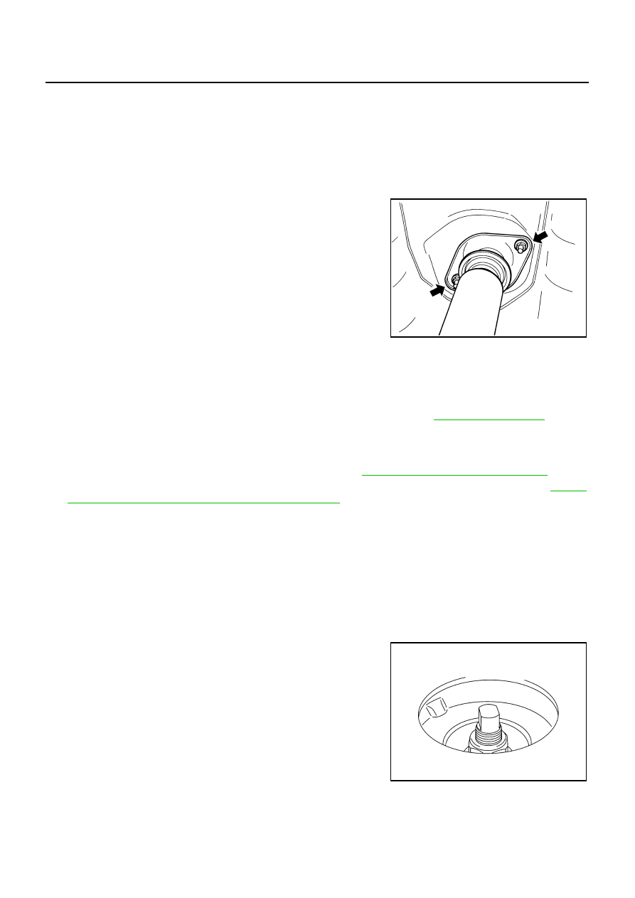
5.
Remove shock absorber assembly upper end nuts with a power
tool, and then remove shock absorber assembly from vehicle.
INSPECTION AFTER REMOVAL
●
Check shock absorber assembly for deformation, cracks, damage, and replace if there are.
●
Check welded and sealed areas for oil leakage, and replace if there are.
INSTALLATION
●
Installation is the reverse order of removal. For tightening torque. Refer to
.
CAUTION:
Do not reuse non-reusable parts.
●
Perform final tightening of shock absorber assembly lower side (rubber bushing) under unladen condition
with tires on level ground. Check wheel alignment. Refer to
RSU-5, "Wheel Alignment Inspection"
●
Adjust neutral position of steering angle sensor after checking the wheel alignment. Refer to
"Adjustment of Steering Angle Sensor Neutral Position"
Disassembly and Assembly
NES000JB
DISASSEMBLY
CAUTION:
Make sure piston rod on shock absorber is not damaged when removing components from shock
absorber.
1.
Remove mounting seal from mounting bracket.
2.
Wrap a shop cloth around lower side of shock absorber and secure it in a vise.
CAUTION:
Do not set the cylindrical part of shock absorber in a vise.
3.
Secure the piston rod tip so that piston rod does not turn, and
remove piston rod lock nut.
4.
Remove washer, distance tube, bushing, bound bumper cover
and bound bumper from shock absorber.
INSPECTION AFTER DISASSEMBLY
Bound Bumper and Bushing
Check bound bumper cover and bushing for cracks and damage. Replace if there are.
FA-0274D
SEIA0218J
SHOCK ABSORBER
RSU-11
C
D
F
G
H
I
J
K
L
M
A
B
RSU
Shock Absorber
Check the following:
●
Shock absorber for deformation, cracks, and other damage. Replace if there are.
●
Piston rod for damage, uneven wear, and distortion. Replace if there are.
ASSEMBLY
●
Installation is the reverse order of removal. For tightening torque. Refer to
CAUTION:
Do not reuse non-reusable parts.
●
Make sure piston rod on shock absorber is not damaged when attaching components to shock absorber.
RSU-12
SUSPENSION ARM
SUSPENSION ARM
PFP:55501
Removal and Installation
NES000JC
REMOVAL
1.
Remove tire with a power tool.
2.
Set a jack under rear lower link to relieve the coil spring tension.
3.
Remove connecting rod mounting bracket from suspension arm with a power tool.
4.
Remove mounting nuts and bolts between suspension arm and rear suspension member.
5.
Remove cotter pin of suspension arm ball joint, and loosen nut.
6.
Use a ball joint remover (suitable tool) to remove suspension arm from axle. Be careful not to damage ball
joint boot.
CAUTION:
Tighten temporarily mounting nut to prevent damage to threads and to prevent ball joint remover
(suitable tool) from coming off.
7.
Remove suspension arm and stopper rubber from vehicle.
INSPECTION AFTER REMOVAL
Visual Inspection
●
Check suspension arm and bushing for deformation, cracks or damage. If any non-standard condition is
found, replace it.
●
Check boot of ball joint for cracks or damage, and also for grease leakage. If a malfunction is detected,
replace suspension arm.
Ball Joint Inspection
Manually move ball stud at least ten times by hand to check for smooth movement.
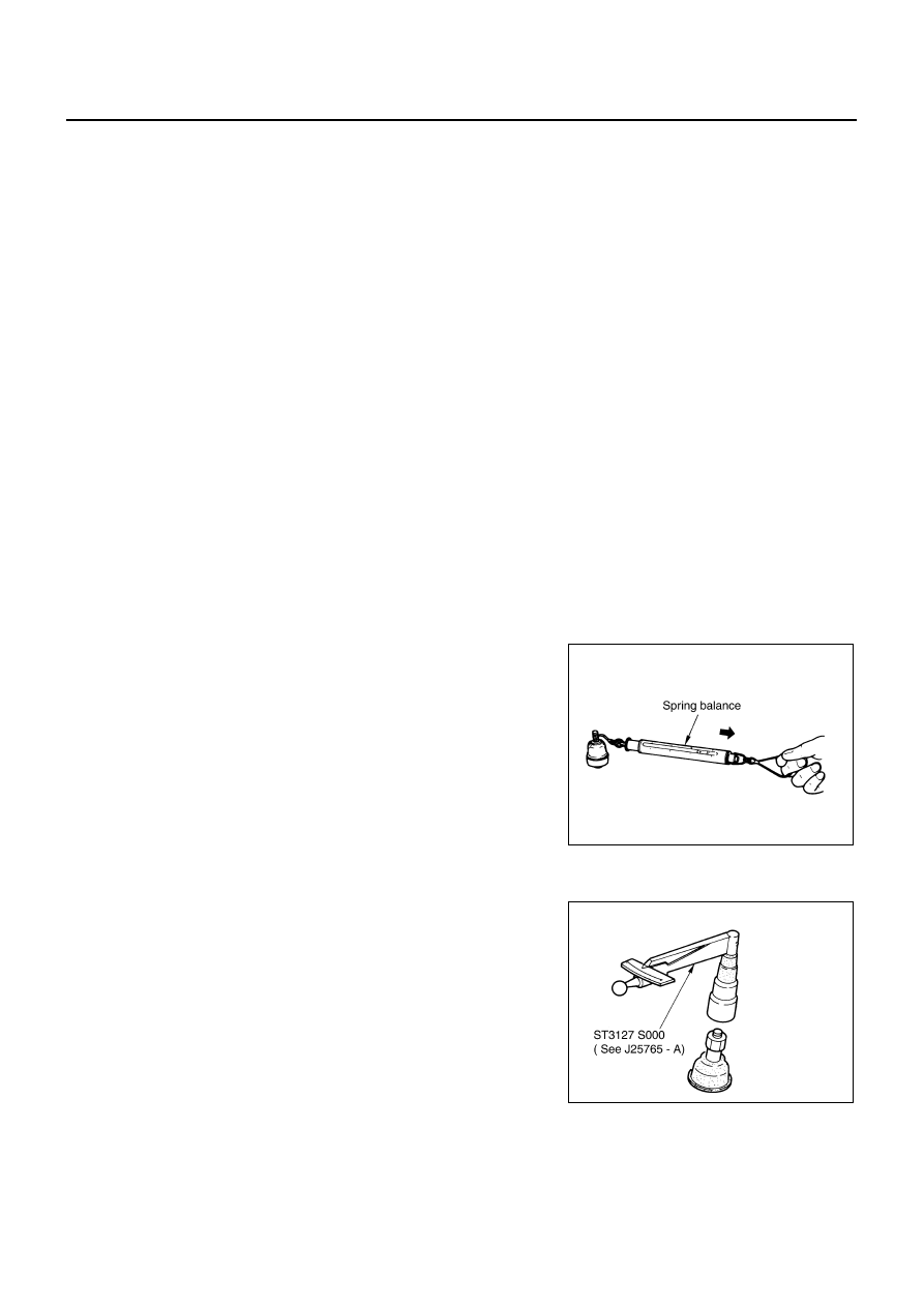
Swing Torque Inspection
●
Hook spring balance at cotter pin mounting hole. Confirm spring
balance measurement value is within specifications when ball
stud begins moving.
●
If it is outside the specified range, replace suspension arm
assembly.
Rotating Torque Inspection
●
Install the mounting nut to ball stud. Make sure that rotating
torque is within the specifications with a preload gauge (SST)
●
If it is outside the specified range, replace suspension arm
assembly.
Axial End Play Inspection
●
Move tip of ball stud in axial direction to check for looseness.
Standard value
Swing torque:
0.5 - 3.4 N·m (0.06 - 0.34 kg-m, 5 - 30 in-lb)
Measured value of spring balance:
8.1 - 54.8 N (0.83 - 5.5 kg, 1.82 - 12.32 lb)
SEIA0523E
Standard value
Rotating torque:
0.5 - 3.4 N·m (0.06 - 0.34 kg-m, 5 - 30 in-lb)
SDIA1150E
Standard value
Axial end play
: 0 mm (0 in)
Нет комментариевНе стесняйтесь поделиться с нами вашим ценным мнением.
Текст