Infiniti M35/M45 Y50. Manual — part 563
INDEX FOR DTC
EC-725
[VK45DE]
C
D
E
F
G
H
I
J
K
L
M
A
EC
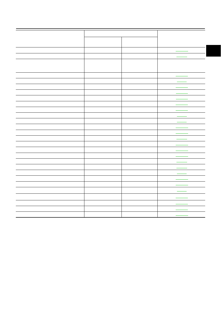
*1: 1st trip DTC No. is the same as DTC No.
*2: This number is prescribed by SAE J2012.
*3: In Diagnostic Test Mode II (Self-diagnostic results), this number is controlled by NISSAN.
*4: The troubleshooting for this DTC needs CONSULT-II.
*5: When the fail-safe operations for both self-diagnoses occur, the MIL illuminates.
*6: Models with ICC.
MULTI CYL MISFIRE
P0300
0300
NATS MALFUNCTION
P1610 - P1615
1610 - 1615
NO DTC IS DETECTED.
FURTHER TESTING
MAY BE REQUIRED.
P0000
0000
—
P-N POS SW/CIRCUIT
P0850
0850
PNP SW/CIRC
P0705
0705
PURG VOLUME CONT/V
P0443
0443
PURG VOLUME CONT/V
P0444
0444
PURG VOLUME CONT/V
P0445
0445
PW ST P SEN/CIRC
P0550
0550
SENSOR POWER/CIRC
P0643
0643
TCC SOLENOID/CIRC
P0740
0740
TCM
P0700
0700
TCS/CIRC
P1212
1212
TCS C/U FUNCTN
P1211
1211
THERMSTAT FNCTN
P0128
0128
TP SENSOR
P2135
2135
TP SEN 1/CIRC
P0222
0222
TP SEN 1/CIRC
P0223
0223
TP SEN 2/CIRC
P0122
0122
TP SEN 2/CIRC
P0123
0123
TURBINE SENSOR
P0717
0717
TW CATALYST SYS-B1
P0420
0420
TW CATALYST SYS-B2
P0430
0430
VEH SPD SEN/CIR AT*
5
P0720
0720
VEH SPEED SEN/CIRC*
5
P0500
0500
VENT CONTROL VALVE
P0447
0447
VENT CONTROL VALVE
P0448
0448
VIAS S/V CIRC
P1800
1800
Items
(CONSULT-II screen terms)
DTC*
1
Reference page
CONSULT-II
GST*
2
ECM*
3

EC-726
[VK45DE]
PRECAUTIONS
PRECAUTIONS
PFP:00001
Precautions for Supplemental Restraint System (SRS) “AIR BAG” and “SEAT
BELT PRE-TENSIONER”
NBS0059C
The Supplemental Restraint System such as “AIR BAG” and “SEAT BELT PRE-TENSIONER”, used along
with a front seat belt, helps to reduce the risk or severity of injury to the driver and front passenger for certain
types of collision. This system includes seat belt switch inputs and dual stage front air bag modules. The SRS
system uses the seat belt switches to determine the front air bag deployment, and may only deploy one front
air bag, depending on the severity of a collision and whether the front occupants are belted or unbelted.
Information necessary to service the system safely is included in the SRS and SB section of this Service Man-
ual.
WARNING:
●
To avoid rendering the SRS inoperative, which could increase the risk of personal injury or death
in the event of a collision which would result in air bag inflation, all maintenance must be per-
formed by an authorized NISSAN/INFINITI dealer.
●
Improper maintenance, including incorrect removal and installation of the SRS, can lead to per-
sonal injury caused by unintentional activation of the system. For removal of Spiral Cable and Air
Bag Module, see the SRS section.
●
Do not use electrical test equipment on any circuit related to the SRS unless instructed to in this
Service Manual. SRS wiring harnesses can be identified by yellow and/or orange harnesses or
harness connectors.
Precautions for Procedures without Cowl Top Cover
NBS0059D
When performing the procedure after removing cowl top cover, cover
the lower end of windshield with urethane, etc.
On Board Diagnostic (OBD) System of Engine and A/T
NBS0059E
The ECM has an on board diagnostic system. It will light up the malfunction indicator lamp (MIL) to warn the
driver of a malfunction causing emission deterioration.
CAUTION:
●
Be sure to turn the ignition switch OFF and disconnect the negative battery cable before any
repair or inspection work. The open/short circuit of related switches, sensors, solenoid valves,
etc. will cause the MIL to light up.
●
Be sure to connect and lock the connectors securely after work. A loose (unlocked) connector will
cause the MIL to light up due to the open circuit. (Be sure the connector is free from water, grease,
dirt, bent terminals, etc.)
●
Certain systems and components, especially those related to OBD, may use a new style slide-
locking type harness connector. For description and how to disconnect, refer to
●
Be sure to route and secure the harnesses properly after work. The interference of the harness
with a bracket, etc. may cause the MIL to light up due to the short circuit.
●
Be sure to connect rubber tubes properly after work. A misconnected or disconnected rubber tube
may cause the MIL to light up due to the malfunction of the EVAP system or fuel injection system,
etc.
●
Be sure to erase the unnecessary malfunction information (repairs completed) from the ECM and
TCM (Transmission control module) before returning the vehicle to the customer.
PIIB3706J

PRECAUTIONS
EC-727
[VK45DE]
C
D
E
F
G
H
I
J
K
L
M
A
EC
Precaution
NBS0059F
●
Always use a 12 volt battery as power source.
●
Do not attempt to disconnect battery cables while engine is
running.
●
Before connecting or disconnecting the ECM harness con-
nector, turn ignition switch OFF and disconnect negative
battery cable. Failure to do so may damage the ECM
because battery voltage is applied to ECM even if ignition
switch is turned OFF.
●
Before removing parts, turn ignition switch OFF and then
disconnect negative battery cable.
●
Do not disassemble ECM.
●
If a battery cable is disconnected, the memory will return to
the ECM value.
The ECM will now start to self-control at its initial value.
Engine operation can vary slightly when the terminal is dis-
connected. However, this is not an indication of a malfunc-
tion. Do not replace parts because of a slight variation.
●
If the battery is disconnected, the following emission-
related diagnostic information will be lost within 24 hours.
–
Diagnostic trouble codes
–
1st trip diagnostic trouble codes
–
Freeze frame data
–
1st trip freeze frame data
–
System readiness test (SRT) codes
–
Test values
●
When connecting ECM harness connector, fasten (B) it
securely with a lever (2) as far as it will go as shown in the
figure.
–
ECM (1)
–
Loosen (A)
●
When connecting or disconnecting pin connectors into or
from ECM, take care not to damage pin terminals (bend or
break).
Make sure that there are not any bends or breaks on ECM
pin terminal, when connecting pin connectors.
●
Securely connect ECM harness connectors.
A poor connection can cause an extremely high (surge)
voltage to develop in coil and condenser, thus resulting in
damage to ICs.
●
Keep engine control system harness at least 10 cm (4 in)
away from adjacent harness, to prevent engine control sys-
tem malfunctions due to receiving external noise, degraded
operation of ICs, etc.
●
Keep engine control system parts and harness dry.
SEF289H
PBIB1164E
PBIB2714E
PBIB0090E
EC-728
[VK45DE]
PRECAUTIONS
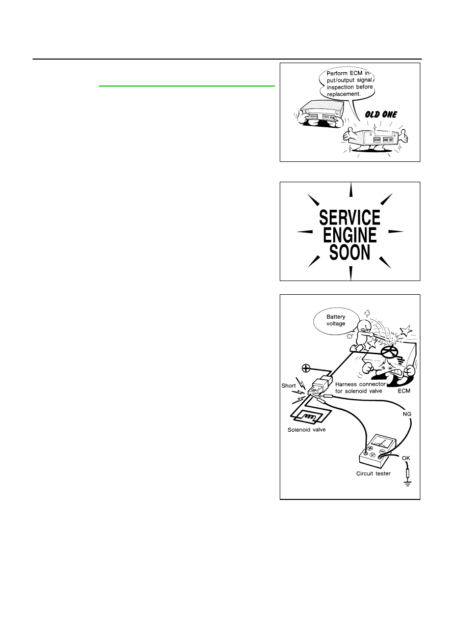
●
Before replacing ECM, perform ECM Terminals and Refer-
ence Value inspection and make sure ECM functions prop-
erly. Refer to
EC-817, "ECM Terminals and Reference Value"
.
●
Handle mass air flow sensor carefully to avoid damage.
●
Do not clean mass air flow sensor with any type of deter-
gent.
●
Do not disassemble electric throttle control actuator.
●
Even a slight leak in the air intake system can cause seri-
ous incidents.
●
Do not shock or jar the camshaft position sensor (PHASE),
crankshaft position sensor (POS).
●
After performing each TROUBLE DIAGNOSIS, perform DTC
Confirmation Procedure or Overall Function Check.
The DTC should not be displayed in the DTC Confirmation
Procedure if the repair is completed. The Overall Function
Check should be a good result if the repair is completed.
●
When measuring ECM signals with a circuit tester, never
allow the two tester probes to contact.
Accidental contact of probes will cause a short circuit and
damage the ECM power transistor.
●
Do not use ECM ground terminals when measuring input/
output voltage. Doing so may result in damage to the ECM's
transistor. Use a ground other than ECM terminals, such as
the ground.
MEF040D
SEF217U
SEF348N
Нет комментариевНе стесняйтесь поделиться с нами вашим ценным мнением.
Текст