Infiniti M35/M45 Y50. Manual — part 113
ATC-3
C
D
E
F
G
H
I
K
L
M
A
B
ATC
INSPECTION FLOW . . . . . . . . . . ..110
Memory Function . . . . . . . . . . . . .. 111
INSPECTION FLOW . . . . . . . . . . .. 111
Ambient Sensor Circuit . . . . . . . . . . .112
COMPONENT DESCRIPTION . . . . . . ..112
AMBIENT TEMPERATURE INPUT PROCESS
In-vehicle Sensor Circuit . . . . . . . . . ...115
Sunload Sensor Circuit . . . . . . . . . . .118
Intake Sensor Circuit . . . . . . . . . . . 121
CONTROLLER . . . . . . . . . . . . . ... 123
Removal and Installation of Multifunction Switch . 123
REMOVAL . . . . . . . . . . . . . . . 123
INSTALLATION . . . . . . . . . . . . . 123
AUTO AMP . . . . . . . . . . . . . . . . 124
Removal and Installation of Unified Meter and A/C
Auto Amp. . . . . . . . . . . . . . . . 124
REMOVAL . . . . . . . . . . . . . . . 124
INSTALLATION . . . . . . . . . . . . . 124
AMBIENT SENSOR . . . . . . . . . . . . 125
Removal and Installation . . . . . . . . . .. 125
REMOVAL . . . . . . . . . . . . . . . 125
INSTALLATION . . . . . . . . . . . . . 125
IN-VEHICLE SENSOR . . . . . . . . . . . 126
Removal and Installation . . . . . . . . . .. 126
REMOVAL . . . . . . . . . . . . . . . 126
INSTALLATION . . . . . . . . . . . . . 126
SUNLOAD SENSOR . . . . . . . . . . . .. 127
Removal and Installation . . . . . . . . . .. 127
REMOVAL . . . . . . . . . . . . . . . 127
INSTALLATION . . . . . . . . . . . . . 127
INTAKE SENSOR . . . . . . . . . . . . ... 128
Removal and Installation . . . . . . . . . .. 128
REMOVAL . . . . . . . . . . . . . . . 128
INSTALLATION . . . . . . . . . . . . . 128
BLOWER UNIT . . . . . . . . . . . . . ... 129
Removal and Installation . . . . . . . . . .. 129
REMOVAL . . . . . . . . . . . . . . . 129
INSTALLATION . . . . . . . . . . . . . 129
Disassembly and Assembly . . . . . . . . . 130
BLOWER MOTOR . . . . . . . . . . . . .. 131
Removal and Installation . . . . . . . . . .. 131
REMOVAL . . . . . . . . . . . . . . . 131
INSTALLATION . . . . . . . . . . . . . 131
INTAKE DOOR MOTOR . . . . . . . . . . . 132
Removal and Installation . . . . . . . . . .. 132
REMOVAL . . . . . . . . . . . . . . . 132
INSTALLATION . . . . . . . . . . . . . 132
IN-CABIN MICROFILTER . . . . . . . . . ... 133
Removal and Installation . . . . . . . . . .. 133
HEATER & COOLING UNIT ASSEMBLY . . . ... 134
Removal and Installation . . . . . . . . . .. 134
REMOVAL . . . . . . . . . . . . . . . 134
INSTALLATION . . . . . . . . . . . . . 135
Disassembly and Assembly . . . . . . . . .. 137
MODE DOOR MOTOR . . . . . . . . . . . 139
Removal and Installation . . . . . . . . . .. 139
REMOVAL . . . . . . . . . . . . . . . 139
INSTALLATION . . . . . . . . . . . . . 139
AIR MIX DOOR MOTOR . . . . . . . . . . . 140
Removal and Installation . . . . . . . . . .. 140
REMOVAL . . . . . . . . . . . . . . . 140
INSTALLATION . . . . . . . . . . . . . 140
UPPER VENTILATOR DOOR MOTOR . . . . .. 141
Removal and Installation . . . . . . . . . .. 141
REMOVAL . . . . . . . . . . . . . . . 141
INSTALLATION . . . . . . . . . . . . . 141
HEATER CORE . . . . . . . . . . . . . ... 142
Removal and Installation . . . . . . . . . .. 142
REMOVAL . . . . . . . . . . . . . . . 142
INSTALLATION . . . . . . . . . . . . . 142
DUCTS AND GRILLES . . . . . . . . . . ... 143
Removal and Installation . . . . . . . . . .. 143
REFRIGERANT LINES . . . . . . . . . . ... 150
HFC-134a (R-134a) Service Procedure . . . ... 150
SETTING OF SERVICE TOOLS AND EQUIP-
MENT . . . . . . . . . . . . . . . . 150
Components . . . . . . . . . . . . . . . 152
VQ35DE . . . . . . . . . . . . . . . 152
VK45DE . . . . . . . . . . . . . . . . 153
Removal and Installation of Compressor . . . .. 153
REMOVAL . . . . . . . . . . . . . . . 153
INSTALLATION . . . . . . . . . . . . . 156
REMOVAL . . . . . . . . . . . . . . . 157
INSTALLATION . . . . . . . . . . . . . 157
Removal and Installation of High-pressure Flexible
Hose . . . . . . . . . . . . . . . . . . 158
REMOVAL . . . . . . . . . . . . . . . 158
INSTALLATION . . . . . . . . . . . . . 159
Removal and Installation of High-pressure Pipe 1
(Engine Compartment) . . . . . . . . . . . 159
REMOVAL . . . . . . . . . . . . . . . 159
INSTALLATION . . . . . . . . . . . . . 160
ATC-4
and High-pressure Pipe 2 . . . . . . . . . . 161
REMOVAL . . . . . . . . . . . . . . . 161
INSTALLATION . . . . . . . . . . . . .. 162
Removal and Installation of Liquid Tank . . . ... 163
Removal and Installation of Condenser . . . . 164
REMOVAL . . . . . . . . . . . . . . . 164
INSTALLATION . . . . . . . . . . . . .. 166
Removal and Installation of Refrigerant Pressure
Sensor . . . . . . . . . . . . . . . . .. 166
REMOVAL . . . . . . . . . . . . . . . 166
INSTALLATION . . . . . . . . . . . . .. 166
Removal and Installation of Evaporator . . . . 167
REMOVAL . . . . . . . . . . . . . . . 167
INSTALLATION . . . . . . . . . . . . .. 167
Removal and Installation of Expansion Valve . ...168
REMOVAL . . . . . . . . . . . . . . ..168
INSTALLATION . . . . . . . . . . . . ..168
PRECAUTIONS
ATC-5
C
D
E
F
G
H
I
K
L
M
A
B
ATC
PRECAUTIONS
PFP:00001
Precautions for Supplemental Restraint System (SRS) “AIR BAG” and “SEAT
BELT PRE-TENSIONER”
NJS000FN
The Supplemental Restraint System such as “AIR BAG” and “SEAT BELT PRE-TENSIONER”, used along
with a front seat belt, helps to reduce the risk or severity of injury to the driver and front passenger for certain
types of collision. This system includes seat belt switch inputs and dual stage front air bag modules. The SRS
system uses the seat belt switches to determine the front air bag deployment, and may only deploy one front
air bag, depending on the severity of a collision and whether the front occupants are belted or unbelted.
Information necessary to service the system safely is included in the SRS and SB section of this Service Man-
ual.
WARNING:
●
To avoid rendering the SRS inoperative, which could increase the risk of personal injury or death
in the event of a collision which would result in air bag inflation, all maintenance must be per-
formed by an authorized NISSAN/INFINITI dealer.
●
Improper maintenance, including incorrect removal and installation of the SRS, can lead to per-
sonal injury caused by unintentional activation of the system. For removal of Spiral Cable and Air
Bag Module, see the SRS section.
●
Do not use electrical test equipment on any circuit related to the SRS unless instructed to in this
Service Manual. SRS wiring harnesses can be identified by yellow and/or orange harnesses or
harness connectors.
Precautions Necessary for Steering Wheel Rotation After Battery Disconnect
NJS000FO
NOTE:
●
This Procedure is applied only to models with Intelligent Key system and NVIS/IVIS (NISSAN/INFINITI
VEHICLE IMMOBILIZER SYSTEM - NATS).
●
Remove and install all control units after disconnecting both battery cables with the ignition knob in the
″
LOCK
″
position.
●
Always use CONSULT-II to perform self-diagnosis as a part of each function inspection after finishing
work. If DTC is detected, perform trouble diagnosis according to self-diagnostic results.
For models equipped with the Intelligent Key system and NVIS/IVIS, an electrically controlled steering lock
mechanism is adopted on the key cylinder.
For this reason, if the battery is disconnected or if the battery is discharged, the steering wheel will lock and
steering wheel rotation will become impossible.
If steering wheel rotation is required when battery power is interrupted, follow the procedure below before
starting the repair operation.
OPERATION PROCEDURE
1.
Connect both battery cables.
NOTE:
Supply power using jumper cables if battery is discharged.
2.
Use the Intelligent Key or mechanical key to turn the ignition switch to the
″
ACC
″
position. At this time, the
steering lock will be released.
3.
Disconnect both battery cables. The steering lock will remain released and the steering wheel can be
rotated.
4.
Perform the necessary repair operation.
5.
When the repair work is completed, return the ignition switch to the
″
LOCK
″
position before connecting
the battery cables. (At this time, the steering lock mechanism will engage.)
6.
Perform a self-diagnosis check of all control units using CONSULT-II.
ATC-6
PRECAUTIONS
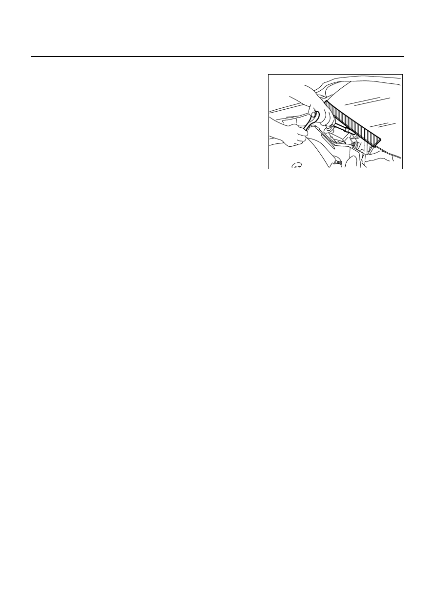
Precautions for Procedures without Cowl Top Cover
NJS000FP
When performing the procedure after removing cowl top cover, cover
the lower end of windshield with urethane, etc.
Precautions for Working with HFC-134a (R-134a)
NJS000FQ
CAUTION:
●
CFC-12 (R-12) refrigerant and HFC-134a (R-134a) refrigerant are not compatible. If the refrigerants
are mixed and compressor malfunction is likely to occur, refer to “CONTAMINATED REFRIGER-
ANT” below. To determine the purity of HFC-134a (R-134a) in the vehicle and recovery tank, use
Refrigerant Recovery/Recycling Recharging equipment and Refrigerant Identifier.
●
Use only specified lubricant for the HFC-134a (R-134a) A/C system and HFC-134a (R-134a) compo-
nents. If lubricant other than that specified is used, compressor malfunction is likely to occur.
●
The specified HFC-134a (R-134a) lubricant rapidly absorbs moisture from the atmosphere. The fol-
lowing handling precautions must be observed:
–
When removing refrigerant components from a vehicle, immediately cap (seal) the component to
minimize the entry of moisture from the atmosphere.
–
When installing refrigerant components to a vehicle, never remove the caps (unseal) until just
before connecting the components. Connect all refrigerant loop components as quickly as possi-
ble to minimize the entry of moisture into system.
–
Only use the specified lubricant from a sealed container. Immediately reseal containers of lubri-
cant. Without proper sealing, lubricant will become moisture saturated and should not be used.
–
Never allow lubricant (Nissan A/C System Oil Type S) to come in contact with styrene foam parts.
Damage may result.
PIIB3706J
Нет комментариевНе стесняйтесь поделиться с нами вашим ценным мнением.
Текст