Infiniti M35/M45 Y50. Manual — part 389
PREPARATION
EC-29
[VQ35DE]
C
D
E
F
G
H
I
J
K
L
M
A
EC
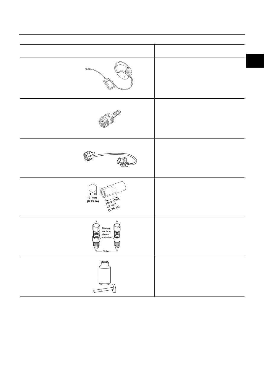
Commercial Service Tools
NBS004S1
Tool name
(Kent-Moore No.)
Description
Leak detector
i.e.: (J-41416)
Locating the EVAP leak
EVAP service port
adapter
i.e.: (J-41413-OBD)
Applying positive pressure through EVAP service
port
Fuel filler cap adapter
i.e.: (MLR-8382)
Checking fuel tank vacuum relief valve opening
pressure
Socket wrench
Removing and installing engine coolant
temperature sensor
Oxygen sensor thread
cleaner
i.e.: (J-43897-18)
(J-43897-12)
Reconditioning the exhaust system threads
before installing a new oxygen sensor. Use with
anti-seize lubricant shown below.
a: 18 mm diameter with pitch 1.5 mm for
Zirconia Oxygen Sensor
b: 12 mm diameter with pitch 1.25 mm for
Titania Oxygen Sensor
Anti-seize lubricant
i.e.: (Permatex
TM
133AR or equivalent
meeting MIL
specification MIL-A-
907)
Lubricating oxygen sensor thread cleaning tool
when reconditioning exhaust system threads.
S-NT703
S-NT704
S-NT815
S-NT705
AEM488
S-NT779
EC-30
[VQ35DE]
ENGINE CONTROL SYSTEM
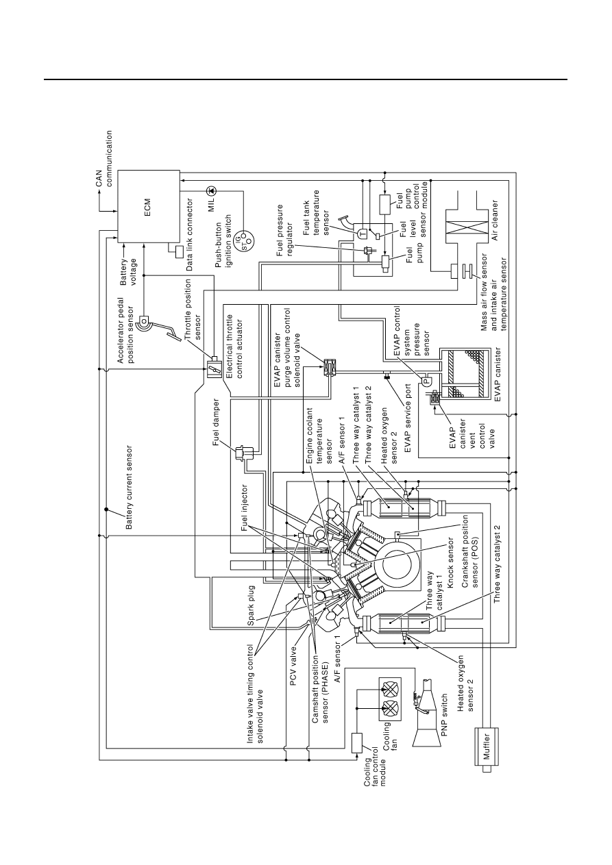
ENGINE CONTROL SYSTEM
PFP:23710
System Diagram
NBS004S2
PBIB2778E

ENGINE CONTROL SYSTEM
EC-31
[VQ35DE]
C
D
E
F
G
H
I
J
K
L
M
A
EC
Multiport Fuel Injection (MFI) System
NBS004S3
INPUT/OUTPUT SIGNAL CHART
*1: This sensor is not used to control the engine system under normal conditions.
*2: This signal is sent to the ECM through CAN communication line.
*3: ECM determines the start signal status by the signals of engine speed and battery voltage.
SYSTEM DESCRIPTION
The amount of fuel injected from the fuel injector is determined by the ECM. The ECM controls the length of
time the valve remains open (injection pulse duration). The amount of fuel injected is a program value in the
ECM memory. The program value is preset by engine operating conditions. These conditions are determined
by input signals (for engine speed and intake air) from the crankshaft position sensor (POS), camshaft position
sensor (PHASE) and the mass air flow sensor.
VARIOUS FUEL INJECTION INCREASE/DECREASE COMPENSATION
In addition, the amount of fuel injected is compensated to improve engine performance under various operat-
ing conditions as listed below.
<Fuel increase>
●
During warm-up
●
When starting the engine
●
During acceleration
●
Hot-engine operation
●
When selector lever is changed from N to D
●
High-load, high-speed operation
<Fuel decrease>
●
During deceleration
●
During high engine speed operation
Sensor
Input Signal to ECM
ECM function
Actuator
Crankshaft position sensor (POS)
Engine speed*
3
Piston position
Fuel injection
& mixture ratio
control
Fuel injector
Camshaft position sensor (PHASE)
Mass air flow sensor
Amount of intake air
Engine coolant temperature sensor
Engine coolant temperature
Air fuel ratio (A/F) sensor 1
Density of oxygen in exhaust gas
Throttle position sensor
Throttle position
Accelerator pedal position sensor
Accelerator pedal position
Park/neutral position (PNP) switch
Gear position
Battery
Battery voltage*
3
Knock sensor
Engine knocking condition
Power steering pressure sensor
Power steering operation
Heated oxygen sensor 2*
1
Density of oxygen in exhaust gas
ABS actuator and electric unit (control unit)
VDC/TCS operation command*
2
Air conditioner switch
Air conditioner operation*
2
Wheel sensor
Vehicle speed*
2

EC-32
[VQ35DE]
ENGINE CONTROL SYSTEM
MIXTURE RATIO FEEDBACK CONTROL (CLOSED LOOP CONTROL)
The mixture ratio feedback system provides the best air-fuel mixture ratio for driveability and emission control.
The three way catalyst 1 can then better reduce CO, HC and NOx emissions. This system uses A/F sensor 1
in the exhaust manifold to monitor whether the engine operation is rich or lean. The ECM adjusts the injection
pulse width according to the sensor voltage signal. For more information about A/F sensor 1, refer to
"DTC P0131, P0151 A/F SENSOR 1"
. This maintains the mixture ratio within the range of stoichiometric (ideal
air-fuel mixture).
This stage is referred to as the closed loop control condition.
Heated oxygen sensor 2 is located downstream of the three way catalyst 1. Even if the switching characteris-
tics of A/F sensor 1 shift, the air-fuel ratio is controlled to stoichiometric by the signal from heated oxygen sen-
sor 2.
Open Loop Control
The open loop system condition refers to when the ECM detects any of the following conditions. Feedback
control stops in order to maintain stabilized fuel combustion.
●
Deceleration and acceleration
●
High-load, high-speed operation
●
Malfunction of A/F sensor 1 or its circuit
●
Insufficient activation of A/F sensor 1 at low engine coolant temperature
●
High engine coolant temperature
●
During warm-up
●
After shifting from N to D
●
When starting the engine
MIXTURE RATIO SELF-LEARNING CONTROL
The mixture ratio feedback control system monitors the mixture ratio signal transmitted from A/F sensor 1.
This feedback signal is then sent to the ECM. The ECM controls the basic mixture ratio as close to the theoret-
ical mixture ratio as possible. However, the basic mixture ratio is not necessarily controlled as originally
designed. Both manufacturing differences (i.e., mass air flow sensor hot wire) and characteristic changes dur-
ing operation (i.e., fuel injector clogging) directly affect mixture ratio.
Accordingly, the difference between the basic and theoretical mixture ratios is monitored in this system. This is
then computed in terms of “injection pulse duration” to automatically compensate for the difference between
the two ratios.
“Fuel trim” refers to the feedback compensation value compared against the basic injection duration. Fuel trim
includes short term fuel trim and long term fuel trim.
“Short term fuel trim” is the short-term fuel compensation used to maintain the mixture ratio at its theoretical
value. The signal from A/F sensor 1 indicates whether the mixture ratio is RICH or LEAN compared to the the-
oretical value. The signal then triggers a reduction in fuel volume if the mixture ratio is rich, and an increase in
fuel volume if it is lean.
“Long term fuel trim” is overall fuel compensation carried out long-term to compensate for continual deviation
of the short term fuel trim from the central value. Such deviation will occur due to individual engine differences,
wear over time and changes in the usage environment.
PBIB3020E
Нет комментариевНе стесняйтесь поделиться с нами вашим ценным мнением.
Текст