Infiniti M35/M45 Y50. Manual — part 1065
AUTOMATIC DRIVE POSITIONER
SE-57
C
D
E
F
G
H
J
K
L
M
A
B
SE
Check Front Lifting Sensor Circuit
NIS0026F
1.
CHECK FUNCTION
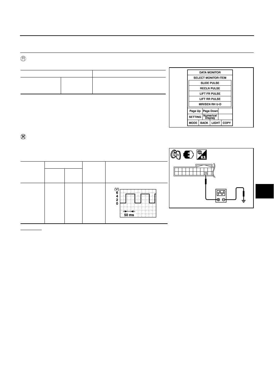
With CONSULT-II
Check operation with “LIFT FR PULSE” on the DATA MONITOR to make sure the pulse changes.
Without CONSULT-II
1.
Turn ignition switch OFF.
2.
Check signal between driver seat control unit connector and
ground, with oscilloscope.
OK or NG
OK
>> Sliding sensor front lifting sensor is OK.
NG
>> GO TO 2.
Monitor item [OPERATION or UNIT]
Contents
LIFT FR PULSE
—
The front lifting position (pulse) judged
from the lifting sensor (front) is dis-
played
PIIA4558E
Sliding
sensor
front lifting
sensor
Terminals
Condition
Signal
(Reference value)
(+)
(–)
B214
25
Ground
Front
lifting
motor
operation
PIIB6153E
PIIA3278E
SE-58
AUTOMATIC DRIVE POSITIONER
2.
CHECK FRONT LIFTING MOTOR SENSOR CIRCUIT HARNESS CONTINUITY
1.
Disconnect driver seat control unit and sliding sensor front lifting sensor connector.
2.
Check continuity between driver seat control unit connector and sliding sensor front lifting sensor connec-
tor.
3.
Check continuity between driver seat control unit connector and
ground.
OK or NG
OK
>> GO TO 3.
NG
>> Repair or replace harness.
3.
CHECK DRIVER SEAT CONTROL UNIT OUTPUT
1.
Connect driver seat control unit connector.
2.
Check voltage between driver seat control unit connector and ground.
OK or NG
OK
>> Replace sliding sensor front lifting sensor.
NG
>> Replace automatic drive positioner control unit.
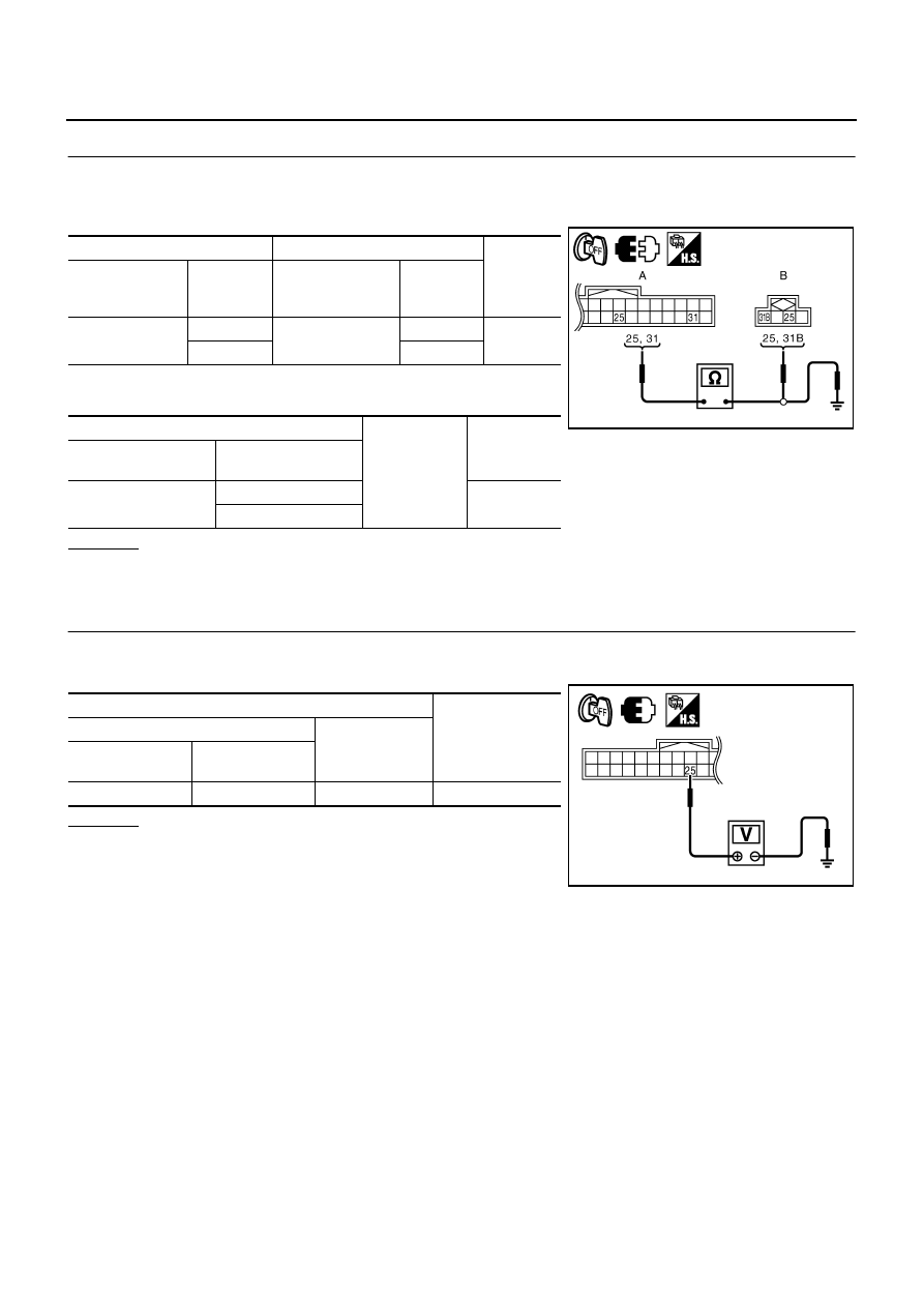
A
B
Continuity
Driver seat control
unit connector
Terminal
Sliding sensor ·
front lifting sensor
connector
Terminal
B204
25
B214
25
Yes
31
31B
A
Ground
Continuity
Driver seat control unit
connector
Terminal
B204
25
No
31
PIIB6154E
Terminals
Voltage (V)
(Approx.)
(+)
(–)
Driver seat control
unit connector
Terminal
B204
25
Ground
5
PIIB6155E
AUTOMATIC DRIVE POSITIONER
SE-59
C
D
E
F
G
H
J
K
L
M
A
B
SE
Check Rear Lifting Sensor Circuit
NIS0026G
1.
CHECK FUNCTION
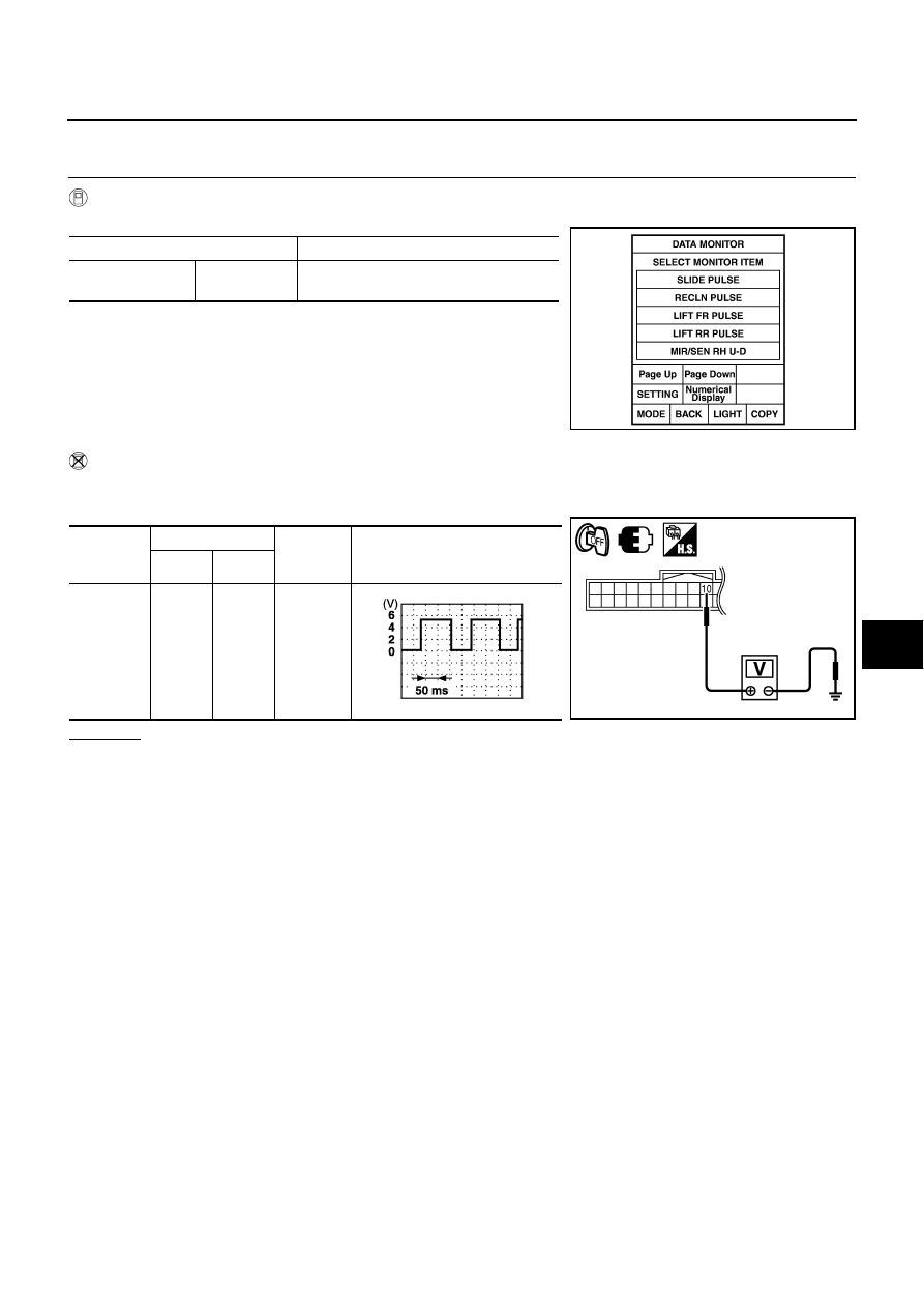
With CONSULT-II
Check operation with “LIFT RR PULSE” on the DATA MONITOR to make sure pulse changes.
Without CONSULT-II
1.
Turn ignition switch OFF.
2.
Check signal between driver seat control unit connector and ground, with oscilloscope.
OK or NG
OK
>> Rear lifting sensor circuit is OK.
NG
>> GO TO 2.
Monitor item [OPERATION or UNIT]
LIFT RR PULSE
—
The rear lifting position (pulse) judged from
the lifting sensor (rear) is displayed.
PIIA4558E
Driver seat
control unit
connector
Terminals
Condition
Signal
(Reference value)
(+)
(–)
B204
10
Ground
Rear
lifting
motor
operation
PIIB6156E
PIIA3278E
SE-60
AUTOMATIC DRIVE POSITIONER
2.
CHECK REAR LIFTING MOTOR SENSOR CIRCUIT HARNESS CONTINUITY
1.
Disconnect driver seat control unit and rear lifting sensor connector.
2.
Check continuity between driver seat control unit connector and
rear lifting sensor connector.
3.
Check continuity between driver seat control unit connector and
ground.
OK or NG
OK
>> GO TO 3.
NG
>> Repair or replace harness.
3.
CHECK DRIVER SEAT CONTROL UNIT OUTPUT
1.
Connect driver seat control unit connector.
2.
Check voltage between driver seat control unit connector and ground.
OK or NG
OK
>> Replace rear lifting sensor.
NG
>> Replace automatic drive positioner control unit.
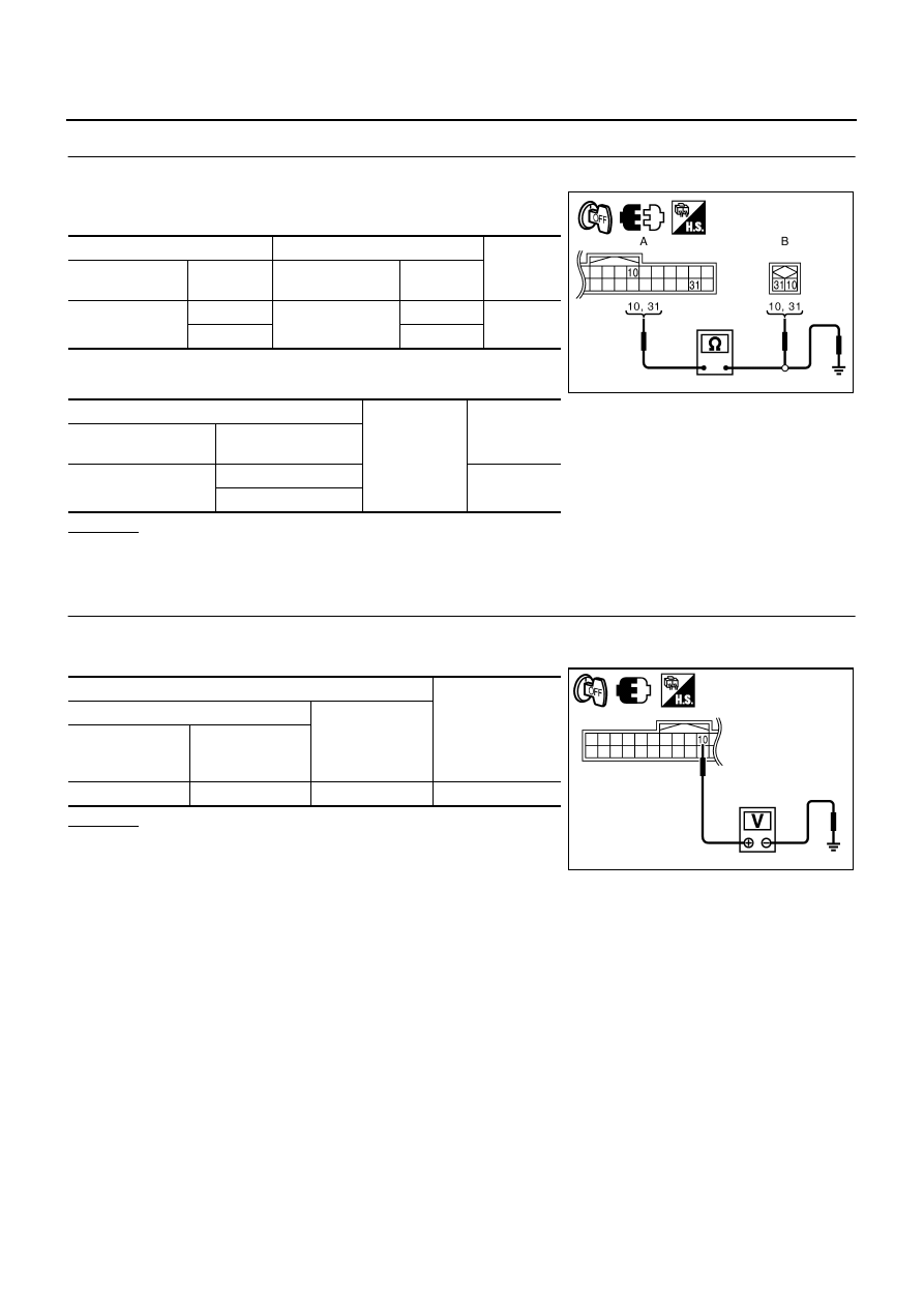
A
B
Continuity
Driver seat control
unit connector
Terminal
Rear lifting sensor
connector
Terminal
B204
10
B218
10
Yes
31
31
A
Ground
Continuity
Driver seat control unit
connector
Terminal
B204
10
No
31
PIIB6157E
Terminals
Voltage (V)
(Approx.)
(+)
(–)
Driver seat
control unit
connector
Terminal
B204
10
Ground
5
PIIB6158E
Нет комментариевНе стесняйтесь поделиться с нами вашим ценным мнением.
Текст