Infiniti M35/M45 Y50. Manual — part 258
INTELLIGENT KEY SYSTEM
BL-101
C
D
E
F
G
H
J
K
L
M
A
B
BL
5.
CHECK INTELLIGENT KEY UNIT OUTPUT SIGNAL
1.
Connect Intelligent Key unit connector.
2.
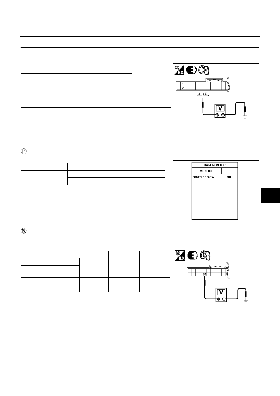
Check voltage between Intelligent Key unit connector and ground.
OK or NG
OK
>> Check the condition of harness and connector.
NG
>> Replace Intelligent Key unit.
Check Trunk Opener Request Switch
NIS001XR
1.
CHECK TRUNK OPENER REQUEST SWITCH
With CONSULT-II
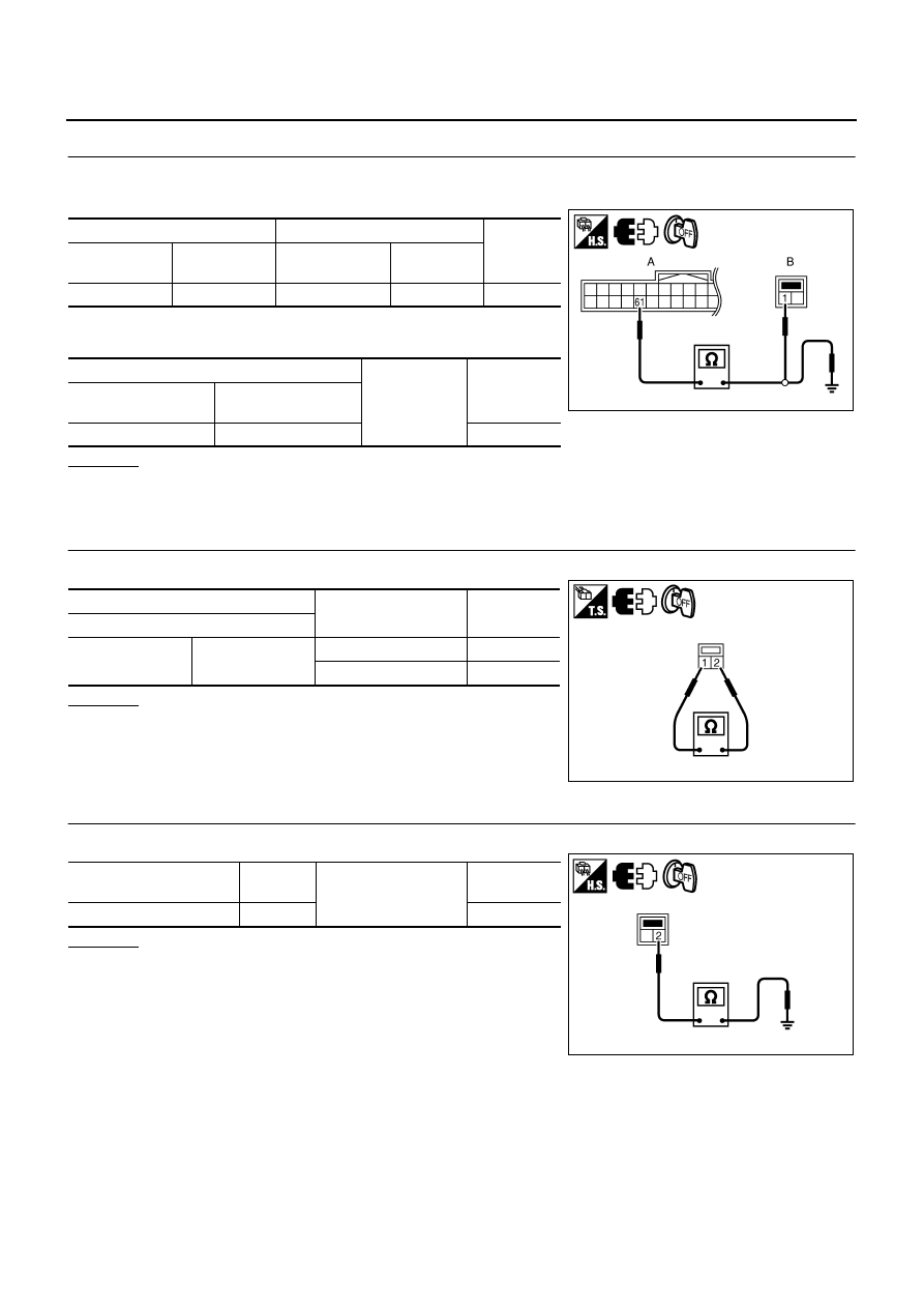
Check trunk opener request switch (“BD/TR REQ SW”) in “DATA MONITOR” mode.
Without CONSULT-II
1.
Turn ignition switch OFF.
2.
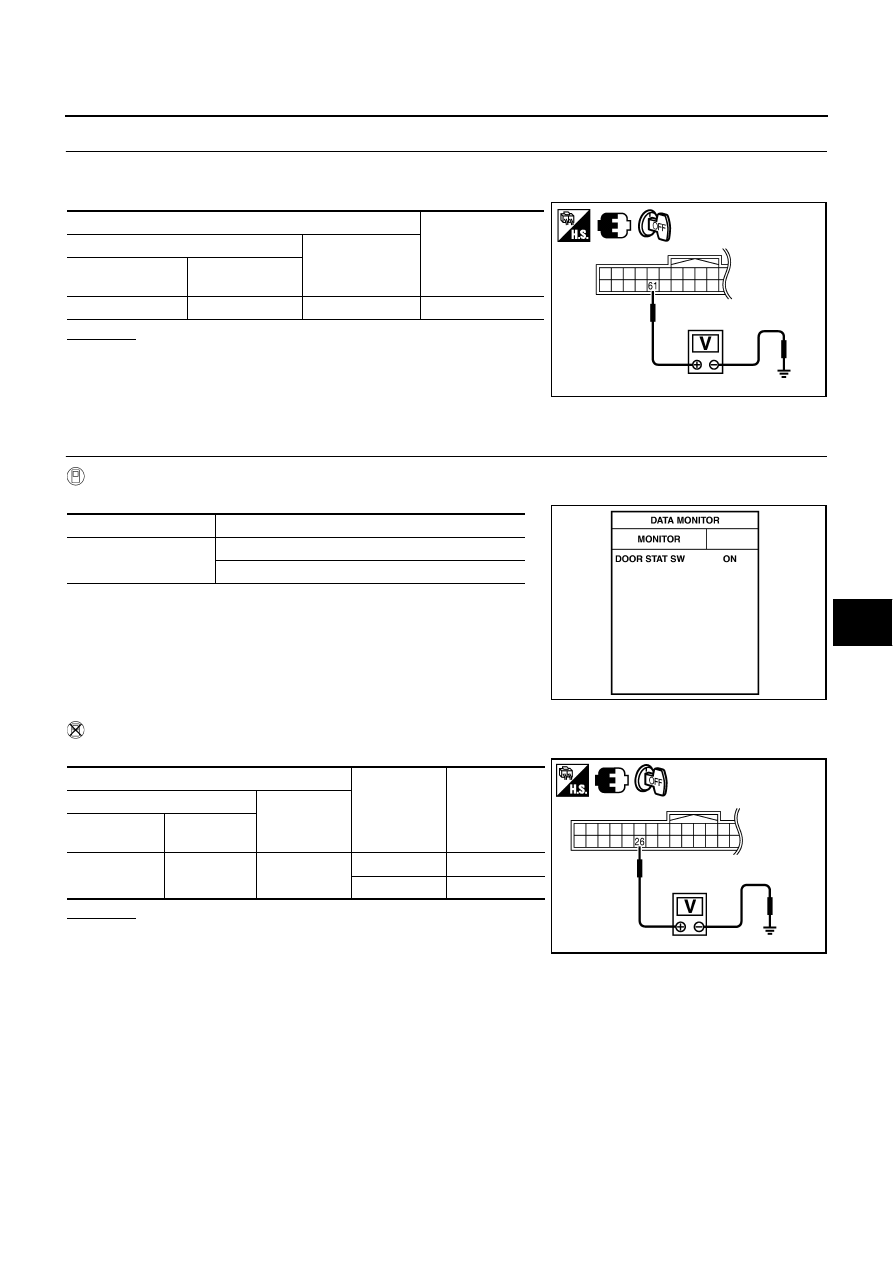
Check voltage between Intelligent Key unit connector and ground.
OK or NG
OK
>> Trunk opener request switch is OK.
NG
>> GO TO 2.
Terminals
Voltage (V)
(Approx.)
(+)
(–)
Intelligent Key unit
connector
Terminal
M32
2
Ground
5
22
PIIB6330E
Monitor item
Condition
BD/TR REQ SW
Trunk opener request switch is pressed: ON
Trunk opener request switch is released: OFF
PIIB4266E
Terminals
Trunk lid
opener
request switch
condition
Voltage (V)
(Approx.)
(+)
(–)
Intelligent Key
unit connector
Terminal
M33
61
Ground
Pressed
0
Released
5
PIIB8990E
BL-102
INTELLIGENT KEY SYSTEM
2.
CHECK TRUNK OPENER REQUEST SWITCH CIRCUIT
1.
Disconnect Intelligent Key unit and trunk opener request switch connector.
2.
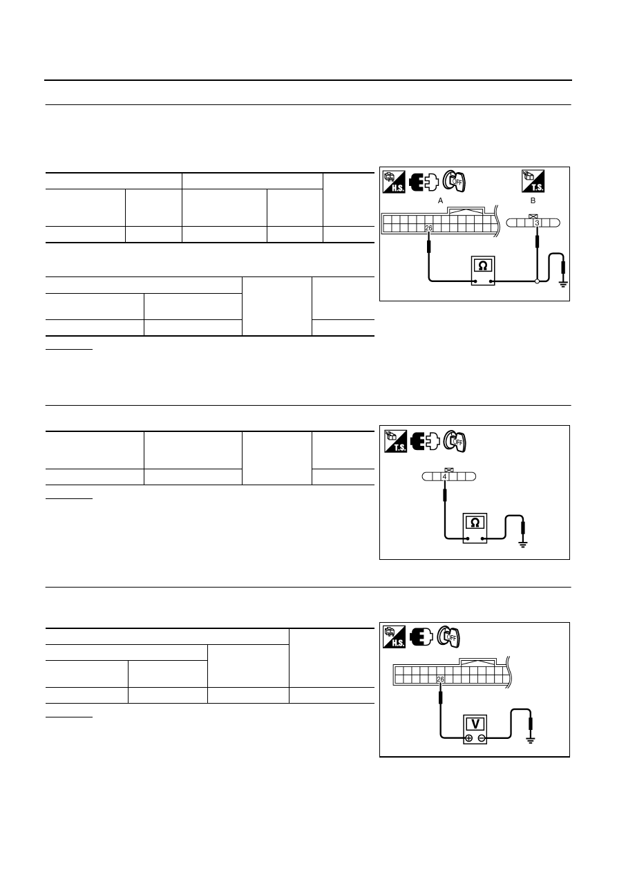
Check continuity between Intelligent Key unit connector and trunk opener request switch connector.
3.
Check continuity between Intelligent Key unit connector and
ground.
OK or NG
OK
>> GO TO 3.
NG
>> Repair or replace harness between Intelligent Key unit and trunk opener request switch.
3.
CHECK TRUNK OPENER REQUEST SWITCH OPERATION
Check trunk opener request switch.
OK or NG
OK
>> GO TO 4.
NG
>> Replace trunk opener request switch.
4.
CHECK TRUNK OPENER REQUEST SWITCH GROUND CIRCUIT
Check continuity between trunk opener request switch connector and ground.
OK or NG
OK
>> GO TO 5.
NG
>> Repair or replace trunk opener request switch ground
circuit.
A
B
Continuity
Intelligent Key
unit connector
Terminal
Trunk request
switch connector
Terminal
M33
61
T107
1
Yes
A
Ground
Continuity
Intelligent Key unit
connector
Terminal
M33
61
No
PIIB8991E
Terminal
Trunk opener request
switch condition
Continuity
Trunk opener request switch
1
2
Pressed
Yes
Released
No
PIIB6336E
Trunk opener request
switch connector
Terminal
Ground
Continuity
T107
2
Yes
PIIB6337E
INTELLIGENT KEY SYSTEM
BL-103
C
D
E
F
G
H
J
K
L
M
A
B
BL
5.
CHECK INTELLIGENT KEY UNIT OUTPUT SIGNAL
1.
Connect Intelligent Key unit connector.
2.
Check voltage between Intelligent Key unit connector and ground.
OK or NG
OK
>> Check the condition of harness and connector.
NG
>> Replace Intelligent Key unit.
Check Unlock Sensor
NIS001XS
1.
CHECK UNLOCK SENSOR POWER SUPPLY
With CONSULT-II
Check unlock sensor (“DOOR STAT SW”) in “DATA MONITOR” mode.
Without CONSULT-II
Check voltage between Intelligent Key unit connector and ground.
OK or NG
OK
>> Unlock sensor is OK.
NG
>> GO TO 2.
Terminals
Voltage (V)
(Approx.)
(+)
(–)
Intelligent Key unit
connector
Terminal
M33
61
Ground
5
PIIB8990E
Monitor item
Condition
DOOR STAT SW
Front door lock (driver side) LOCK: ON
Front door lock (driver side) UNLOCK: OFF
PIIB6399E
Terminals
Front door
lock
(driver side)
condition
Voltage (V)
(Approx.)
(+)
(–)
Intelligent Key
unit connector
Terminal
M32
26
Ground
Locked
Battery voltage
Unlocked
0
PIIB6338E
BL-104
INTELLIGENT KEY SYSTEM
2.
CHECK UNLOCK SENSOR CIRCUIT
1.
Turn ignition switch OFF.
2.
Disconnect Intelligent Key unit and front door lock assembly (driver side) connector.
3.
Check continuity between Intelligent Key unit connector and front door lock assembly (driver side) con-
nector.
4.
Check continuity between Intelligent Key unit connector and
ground.
OK or NG
OK
>> GO TO 3.
NG
>> Repair or replace harness between Intelligent Key unit and front door lock assembly (driver side).
3.
CHECK UNLOCK SENSOR GROUND CIRCUIT
Check continuity between front door lock assembly (driver side) connector and ground.
OK or NG
OK
>> GO TO 4.
NG
>> Repair or replace harness.
4.
CHECK INTELLIGENT KEY UNIT OUTPUT SIGNAL
1.
Connect Intelligent Key unit harness connector.
2.
Check voltage between Intelligent Key unit connector and ground.
OK or NG
OK
>> Replace front door lock assembly (driver side).
NG
>> Replace Intelligent Key unit.
A
B
Continuity
Intelligent Key
unit connector
Terminal
Front door lock
assembly (driver
side) connector
Terminal
M32
26
D14
3
Yes
A
Ground
Continuity
Intelligent Key unit
connector
Terminal
M32
26
No
PIIB6339E
Front door lock
assembly (driver side)
connector
Terminal
Ground
Continuity
D14
4
Yes
PIIB8992E
Terminals
Voltage (V)
(Approx.)
(+)
(–)
Intelligent Key unit
connector
Terminal
M32
26
Ground
Battery voltage
PIIB6338E
Нет комментариевНе стесняйтесь поделиться с нами вашим ценным мнением.
Текст