Infiniti M35/M45 Y50. Manual — part 870
HEADLAMP (FOR USA) - CONVENTIONAL TYPE -
LT-25
C
D
E
F
G
H
I
J
L
M
A
B
LT
CONSULT-II Functions (IPDM E/R)
NKS003O9
CONSULT-II can display each diagnostic item using the diagnostic test mode shown following.
CONSULT-II BASIC OPERATION
Refer to
GI-38, "CONSULT-II Start Procedure"
.
DATA MONITOR
Operation Procedure
1.
Touch “DATA MONITOR” on “SELECTION DIAG MODE ” screen.
2.
Touch “ALL SIGNALS”, “MAIN SIGNALS” or “SELECTION FROM MENU” on the “SELECT MONITOR
ITEM” screen.
3.
When “SELECTION FROM MENU” is selected, touch individual items to be monitored. In “ALL SIG-
NALS”, all items are monitored. In “MAIN SIGNALS”, predetermined items are monitored.
4.
Touch “START”.
5.
Touch “RECORD” while monitoring to record the status of the item being monitored. To stop recording,
touch “STOP”.
All Signals, Main Signals, Selection From Menu
NOTE:
Perform monitoring of IPDM E/R data with the ignition switch ON. When the ignition switch is at ACC, the display may not be correct.
ACTIVE TEST
Operation Procedure
1.
Touch “ACTIVE TEST” on “SELECT DIAG MODE” screen.
2.
Touch item to be tested, and check operation.
3.
Touch “START”.
4.
Touch “STOP” while testing to stop the operation.
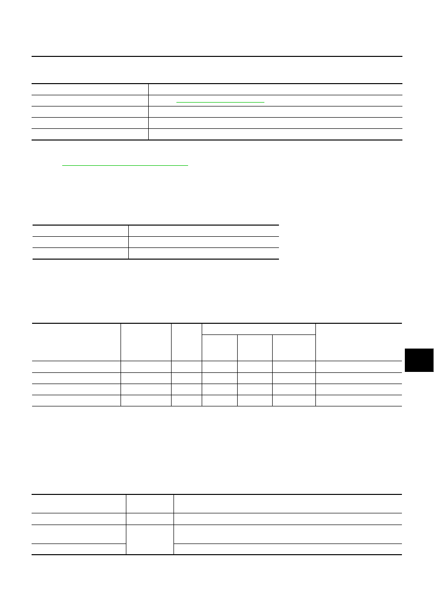
Diagnosis Mode
Description
SELF-DIAGNOSTIC RESULTS
Refer to
DATA MONITOR
The input/output data of IPDM E/R is displayed in real time.
CAN DIAG SUPPORT MNTR
The result of transmit/receive diagnosis of CAN communication can be read.
ACTIVE TEST
IPDM E/R sends a drive signal to electronic components to check their operation.
ALL SIGNALS
Monitors all items.
MAIN SIGNALS
Monitors the predetermined item.
SELECTION FROM MENU
Selects items and monitors them.
Item name
CONSULT-II
screen display
Display
or unit
Monitor item selection
Description
ALL
SIGNALS
MAIN
SIGNALS
SELECTION
FROM
MENU
Position lights request
TAIL&CLR REQ
ON/OFF
×
×
×
Signal status input from BCM
Headlamp low beam request
HL LO REQ
ON/OFF
×
×
×
Signal status input from BCM
Headlamp high beam request
HL HI REQ
ON/OFF
×
×
×
Signal status input from BCM
Front fog lights request
FR FOG REQ
ON/OFF
×
×
×
Signal status input from BCM
Test item
CONSULT-II
screen display
Description
Tail lamp relay output
TAIL LAMP
Allows tail lamp relay to operate by switching operation ON-OFF at your option.
Headlamp relay (HI, LO) output
LAMPS
Allows headlamp relay (HI, LO) to operate by switching operation (OFF, HI ON,
LO ON) at your option (Headlamp high beam repeats ON-OFF every 1 second).
Front fog lamp relay output
Allows fog lamp relay to operate by switching operation ON-OFF at your option.
LT-26
HEADLAMP (FOR USA) - CONVENTIONAL TYPE -
Headlamp High Beam Does Not Illuminate (Both Sides)
NKS003OA
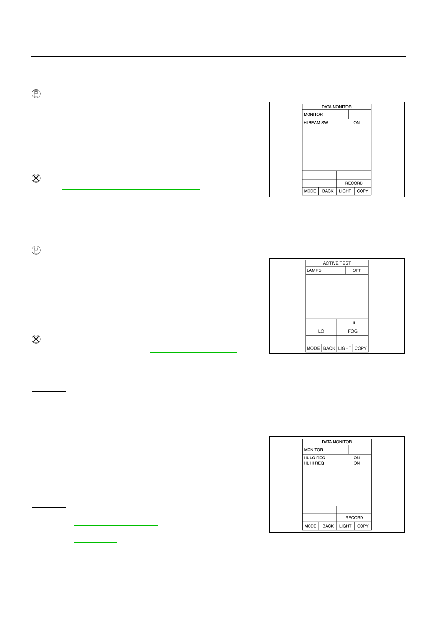
1.
CHECK COMBINATION SWITCH INPUT SIGNAL
With CONSULT-II
1.
Select “BCM” on CONSULT-II. Select “HEAD LAMP” on
“SELECT TEST ITEM” screen.
2.
Select “DATA MONITOR” on “SELECT DIAG MODE” screen.
Make sure that “HI BEAM SW” turns ON-OFF linked with opera-
tion of lighting switch.
Without CONSULT-II
Refer to
LT-239, "Combination Switch Inspection"
OK or NG
OK
>> GO TO 2.
NG
>> Check combination switch (lighting switch). Refer to
LT-239, "Combination Switch Inspection"
2.
HEADLAMP ACTIVE TEST
With CONSULT-II
1.
Select “IPDM E/R” on CONSULT-II. Select “ACTIVE TEST” on
“SELECT DIAG MODE” screen.
2.
Select “LAMPS” on “SELECT TEST ITEM” screen.
3.
Touch “HI” screen.
4.
Make sure headlamp high beam operation.
Without CONSULT-II
1.
Start auto active test. Refer to
2.
Make sure headlamp high beam operation.
OK or NG
OK
>> GO TO 3.
NG
>> GO TO 4.
3.
CHECK IPDM E/R
1.
Select “IPDM E/R” on CONSULT-II. Select “DATA MONITOR”
on “SELECT DIAG MODE” screen.
2.
Make sure “HL LO REQ” and “HL HI REQ” turns ON when light-
ing switch is in HI position.
OK or NG
OK
NG
>> Replace BCM. Refer to
BCS-15, "Removal and Installa-
When lighting switch is
HIGH position
: HI BEAM SW ON
PKIA7585E
Headlamp high beam should operate
(Headlamp high beam repeats ON–OFF every 1 second).
Headlamp high beam should operate.
SKIA5774E
When lighting switch is
HIGH position
: HL LO REQ ON
: HL HI REQ ON
PKIA7638E
HEADLAMP (FOR USA) - CONVENTIONAL TYPE -
LT-27
C
D
E
F
G
H
I
J
L
M
A
B
LT
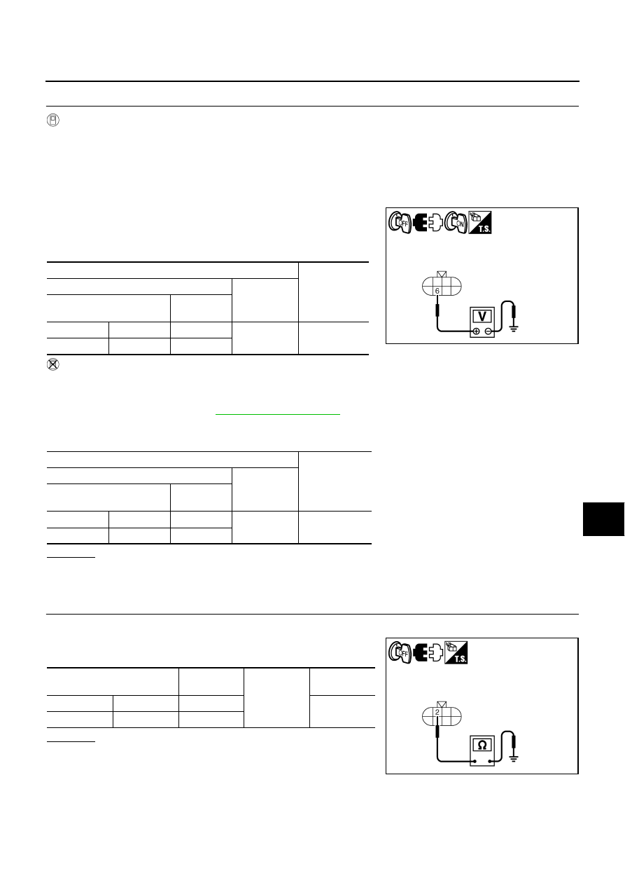
4.
CHECK HEADLAMP INPUT SIGNAL
With CONSULT-II
1.
Turn ignition switch OFF.
2.
Disconnect front combination lamp RH and LH connector.
3.
Select “IPDM E/R” on CONSULT-II, select “ACTIVE TEST” on “SELECT DIAG MODE” screen.
4.
Select “LAMPS” on “SELECT TEST ITEM” screen.
5.
Touch “HI” screen.
6.
When headlamp high beam is operating, check voltage between
front combination lamp (RH and LH) harness connector and
ground. (Headlamp high beam repeats ON-OFF every 1 sec-
ond.)
Without CONSULT-II
1.
Turn ignition switch OFF.
2.
Disconnect front combination lamp connector.
3.
Start auto active test. Refer to
.
4.
When headlamp high beam is operating, check voltage between front combination lamp (RH and LH) har-
ness connector and ground.
OK or NG
OK
>> GO TO 5.
NG
>> GO TO 7.
5.
CHECK HEADLAMP GROUND
1.
Turn ignition switch OFF.
2.
Check continuity between front combination lamp (RH and LH)
harness connector and ground.
OK or NG
OK
>> GO TO 6.
NG
>> Repair harness or connector.
Terminal
Voltage
(Approx.)
(+)
(-)
Front combination lamp
connector
Terminal
RH
E47
6
Ground
Battery voltage
LH
E54
6
Terminal
Voltage
(Approx.)
(+)
(-)
Front combination lamp
connector
Terminal
RH
E47
6
Ground
Battery voltage
LH
E54
6
SKIB4749E
Front combination lamp
connector
Terminal
Ground
Continuity
RH
E47
2
Yes
LH
E54
2
SKIB4750E
LT-28
HEADLAMP (FOR USA) - CONVENTIONAL TYPE -
6.
CHECK BULB
Check bulbs of lamp (both side).
OK or NG
OK
>> Check connecting condition headlamp harness connector.
NG
>> Replace headlamp bulb.
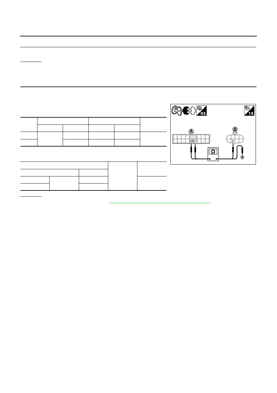
7.
CHECK CIRCUIT BETWEEN IPDM E/R AND FRONT COMBINATION LAMP
1.
Turn ignition switch OFF.
2.
Disconnect IPDM E/R connector.
3.
Check continuity between IPDM E/R harness connector (A) and
front combination lamp (RH and LH) harness connector (B).
4.
Check continuity between IPDM E/R harness connector (A) and
ground.
OK or NG
OK
PG-31, "Removal and Installation of IPDM E/R"
NG
>> Repair harness or connector.
Circuit
A
B
Continuity
Connector
Terminal
Connector
Terminal
RH
E7
27
E47
6
Yes
LH
28
E54
6
A
Ground
Continuity
Connector
Terminal
RH
E7
27
No
LH
28
SKIB4753E
Нет комментариевНе стесняйтесь поделиться с нами вашим ценным мнением.
Текст