Infiniti M35/M45 Y50. Manual — part 665

DTC P0448 EVAP CANISTER VENT CONTROL VALVE
EC-1133
[VK45DE]
C
D
E
F
G
H
I
J
K
L
M
A
EC
Specification data are reference values and are measured between each terminal and ground.
CAUTION:
Do not use ECM ground terminals when measuring input/output voltage. Doing so may result in dam-
age to the ECM's transistor. Use a ground other than ECM terminals, such as the ground.
Diagnostic Procedure
NBS005HW
1.
CHECK RUBBER TUBE
1.
Turn ignition switch OFF.
2.
Disconnect rubber tube connected to EVAP canister vent control
valve (1).
–
Illustration shows the view from under the vehicle.
–
: Vehicle front
–
EVAP canister (2)
–
EVAP control system pressure sensor (3)
3.
Check the rubber tube for clogging.
OK or NG
OK
>> GO TO 2.
NG
>> Clean rubber tube using an air blower.
2.
CHECK EVAP CANISTER VENT CONTROL VALVE
Refer to
EC-1134, "EVAP CANISTER VENT CONTROL VALVE"
OK or NG
OK
>> GO TO 3.
NG
>> Replace EVAP canister vent control valve.
3.
CHECK IF EVAP CANISTER SATURATED WITH WATER
1.
Remove EVAP canister with EVAP canister vent control valve and EVAP control system pressure sensor
attached.
2.
Check if water will drain from the EVAP canister (1).
–
EVAP canister vent control valve (2)
Yes or No
Yes
>> GO TO 4.
No
>> GO TO 6.
TER-
MINAL
NO.
WIRE
COLOR
ITEM
CONDITION
DATA (DC Voltage)
111
SB
ECM relay
(Self shut-off)
[Engine is running]
[Ignition switch: OFF]
●
For a few seconds after turning ignition
switch OFF
0 - 1.5V
[Ignition switch: OFF]
●
More than a few seconds after turning igni-
tion switch OFF
BATTERY VOLTAGE
(11 - 14V)
117
GR/L
EVAP canister vent control
valve
[Ignition switch: ON]
BATTERY VOLTAGE
(11 - 14V)
119
120
R
R
Power supply for ECM
[Ignition switch: ON]
BATTERY VOLTAGE
(11 - 14V)
PBIB2702E
PBIB2731E

EC-1134
[VK45DE]
DTC P0448 EVAP CANISTER VENT CONTROL VALVE
4.
CHECK EVAP CANISTER
Weigh the EVAP canister with the EVAP canister vent control valve and EVAP control system pressure sensor
attached.
The weight should be less than 2.0 kg (4.4 lb).
OK or NG
OK
>> GO TO 6.
NG
>> GO TO 5.
5.
DETECT MALFUNCTIONING PART
Check the following.
●
EVAP canister for damage
●
EVAP hose between EVAP canister and vehicle frame for clogging or poor connection
>> Repair hose or replace EVAP canister.
6.
CHECK EVAP CONTROL SYSTEM PRESSURE SENSOR CONNECTOR
1.
Disconnect EVAP control system pressure sensor harness connector.
2.
Check connectors for water.
OK or NG
OK
>> GO TO 7.
NG
>> Replace EVAP control system pressure sensor.
7.
CHECK EVAP CONTROL SYSTEM PRESSURE SENSOR
Refer to
EC-1144, "Component Inspection"
.
OK or NG
OK
>> GO TO 8.
NG
>> Replace EVAP control system pressure sensor.
8.
CHECK INTERMITTENT INCIDENT
Refer to
EC-857, "TROUBLE DIAGNOSIS FOR INTERMITTENT INCIDENT"
.
>> INSPECTION END
Component Inspection
NBS005HX
EVAP CANISTER VENT CONTROL VALVE
With CONSULT-II
1.
Remove EVAP canister vent control valve from EVAP canister.
2.
Check portion (B) of EVAP canister vent control valve for being
rusted.
If NG, replace EVAP canister vent control valve.
If OK, go to next step.
3.
Reconnect harness connectors disconnected.
4.
Turn ignition switch ON.
Water should not exist.
PBIB1033E

DTC P0448 EVAP CANISTER VENT CONTROL VALVE
EC-1135
[VK45DE]
C
D
E
F
G
H
I
J
K
L
M
A
EC
5.
Perform “VENT CONTROL/V” in “ACTIVE TEST” mode.
6.
Check air passage continuity and operation delay time.
Make sure new O-ring is installed properly.
Operation takes less than 1 second.
If NG, replace EVAP canister vent control valve.
If OK, go to next step.
7.
Clean the air passage [portion (A) to (B)] of EVAP canister vent control valve using an air blower.
8.
Perform step 6 again.
Without CONSULT-II
1.
Remove EVAP canister vent control valve from EVAP canister.
2.
Check portion (B) of EVAP canister vent control valve for being
rusted.
3.
Check air passage continuity and operation delay time under the
following conditions.
Make sure new O-ring is installed properly.
Operation takes less than 1 second.
If NG, replace EVAP canister vent control valve.
If OK, go to next step.
4.
Clean the air passage [portion (A) to (B)] of EVAP canister vent control valve using an air blower.
5.
Perform step 3 again.
Condition VENT CONTROL/V
Air passage continuity between (A) and (B)
ON
No
OFF
Yes
PBIB1679E
PBIB1033E
Condition
Air passage continuity between (A) and (B)
12V direct current supply between
terminals (1) and (2)
No
OFF
Yes
PBIB1034E
EC-1136
[VK45DE]
DTC P0451 EVAP CONTROL SYSTEM PRESSURE SENSOR
DTC P0451 EVAP CONTROL SYSTEM PRESSURE SENSOR
PFP:22365
Component Description
NBS005HY
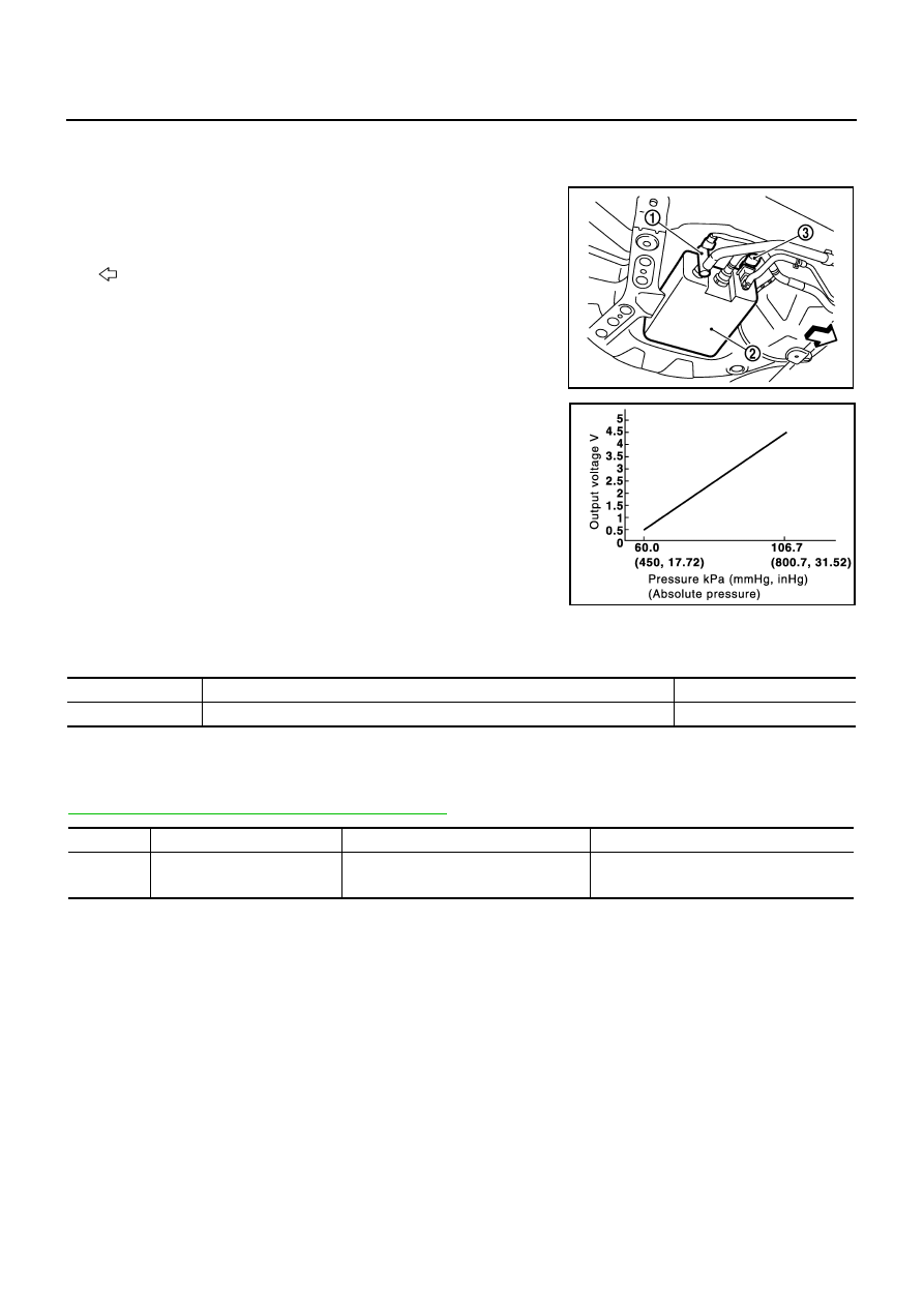
The EVAP control system pressure sensor (3) detects pressure in
the purge line. The sensor output voltage to the ECM increases as
pressure increases.
●
Illustration shows the view from under the vehicle.
●
: Vehicle front
●
EVAP canister vent control valve (1)
●
EVAP canister (2)
CONSULT-II Reference Value in Data Monitor Mode
NBS005HZ
Specification data are reference values.
On Board Diagnosis Logic
NBS005I0
NOTE:
If DTC P0451 is displayed with DTC P0643, first perform the trouble diagnosis for DTC P0643. Refer to
EC-1193, "DTC P0643 SENSOR POWER SUPPLY"
.
PBIB2702E
PBIB1207E
MONITOR ITEM
CONDITION
SPECIFICATION
EVAP SYS PRES
●
Ignition switch: ON
Approx. 1.8 - 4.8V
DTC No.
Trouble diagnosis name
DTC detecting condition
Possible cause
P0451
0451
EVAP control system pressure
sensor performance
ECM detects a sloshing signal from the
EVAP control system pressure sensor
●
Harness or connectors
●
EVAP control system pressure sensor
Нет комментариевНе стесняйтесь поделиться с нами вашим ценным мнением.
Текст