Infiniti M35/M45 Y50. Manual — part 459
DTC P0171, P0174 FUEL INJECTION SYSTEM FUNCTION
EC-309
[VQ35DE]
C
D
E
F
G
H
I
J
K
L
M
A
EC
DTC P0171, P0174 FUEL INJECTION SYSTEM FUNCTION
PFP:16600
On Board Diagnosis Logic
NBS004XS
With the Air/Fuel Mixture Ratio Self-Learning Control, the actual mixture ratio can be brought closely to the
theoretical mixture ratio based on the mixture ratio feedback signal from the A/F sensors 1. The ECM calcu-
lates the necessary compensation to correct the offset between the actual and the theoretical ratios.
In case the amount of the compensation value is extremely large (The actual mixture ratio is too lean.), the
ECM judges the condition as the fuel injection system malfunction and lights up the MIL (2 trip detection logic).
DTC Confirmation Procedure
NBS004XT
NOTE:
If DTC Confirmation Procedure has been previously conducted, always turn ignition switch OFF and wait at
least 10 seconds before conducting the next test.
WITH CONSULT-II
1.
Start engine and warm it up to normal operating temperature.
2.
Turn ignition switch OFF and wait at least 10 seconds.
3.
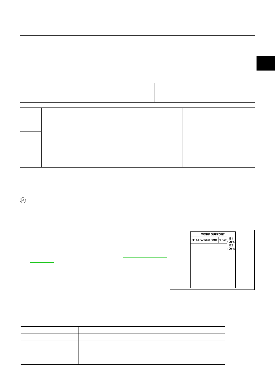
Turn ignition switch ON and select “SELF-LEARNING CONT” in “WORK SUPPORT” mode with CON-
SULT-II.
4.
Clear the self-learning control coefficient by touching “CLEAR”.
5.
Select “DATA MONITOR” mode with CONSULT-II.
6.
Start engine again and let it idle for at least 10 minutes.
The 1st trip DTC P0171 or P0174 should be detected at this
stage, if a malfunction exists. If so, go to
NOTE:
If 1st trip DTC is not detected during above procedure, perform-
ing the following procedure is advised.
a.
Turn ignition switch OFF and wait at least 10 seconds.
b.
Start engine and drive the vehicle under the similar conditions to
(1st trip) Freeze Frame Data for 10 minutes. Refer to the table below.
Hold the accelerator pedal as steady as possible.
The similar conditions to (1st trip) Freeze Frame Data means the vehicle operation that the following con-
ditions should be satisfied at the same time.
Sensor
Input signal to ECM
ECM function
Actuator
A/F sensor 1
Density of oxygen in exhaust gas
(Mixture ratio feedback signal)
Fuel injection control
Fuel injector
DTC No.
Trouble diagnosis name
DTC detecting condition
Possible cause
P0171
0171
(Bank 1)
Fuel injection system too
lean
●
Fuel injection system does not operate properly.
●
The amount of mixture ratio compensation is too
large. (The mixture ratio is too lean.)
●
Intake air leaks
●
A/F sensor 1
●
Fuel injector
●
Exhaust gas leaks
●
Incorrect fuel pressure
●
Lack of fuel
●
Mass air flow sensor
●
Incorrect PCV hose connection
P0174
0174
(Bank 2)
SEF968Y
Engine speed
Engine speed in the freeze frame data
±
400 rpm
Vehicle speed
Vehicle speed in the freeze frame data
±
10 km/h (6 MPH)
Engine coolant temperature
(T) condition
When the freeze frame data shows lower than 70
°
C (158
°
F),
T should be lower than 70
°
C (158
°
F).
When the freeze frame data shows higher than or equal to 70
°
C (158
°
F),
T should be higher than or equal to 70
°
C (158
°
F).
EC-310
[VQ35DE]
DTC P0171, P0174 FUEL INJECTION SYSTEM FUNCTION
7.
If it is difficult to start engine at step 6, the fuel injection system has a malfunction, too.
8.
Crank engine while depressing accelerator pedal. If engine starts, go to
EC-315, "Diagnostic Procedure"
.
If engine does not start, check exhaust and intake air leak visually.
WITH GST
1.
Start engine and warm it up to normal operating temperature.
2.
Turn ignition switch OFF and wait at least 10 seconds.
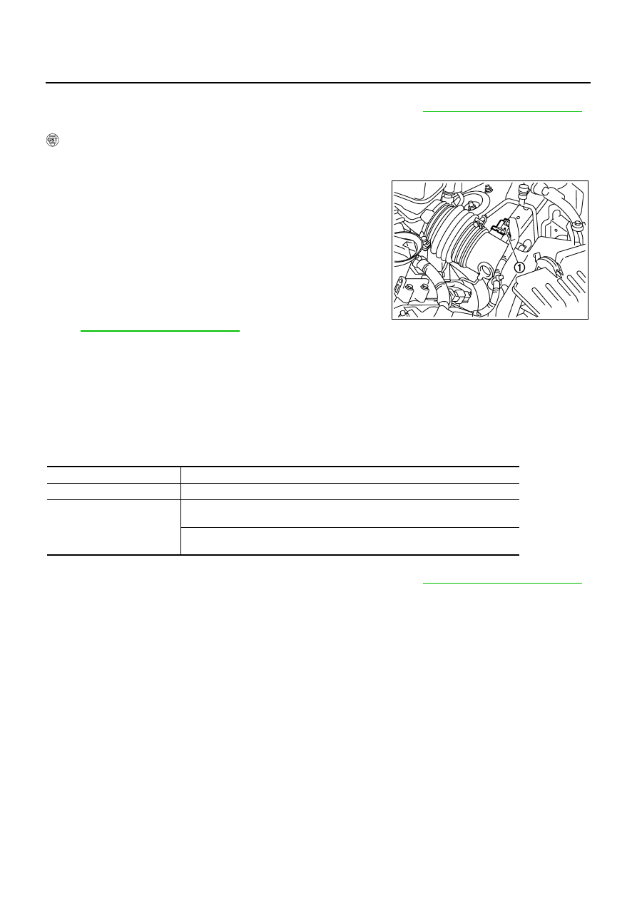
3.
Disconnect mass air flow sensor (1) harness connector.
4.
Restart engine and let it idle for at least 5 seconds.
5.
Stop engine and reconnect mass air flow sensor harness con-
nector.
6.
Select Service $03 with GST. Make sure DTC P0102 is
detected.
7.
Select Service $04 with GST and erase the DTC P0102.
8.
Start engine again and let it idle for at least 10 minutes.
9.
Select Service $07 with GST. The 1st trip DTC P0171 or P0174
should be detected at this stage, if a malfunction exists. If so, go
to
EC-315, "Diagnostic Procedure"
NOTE:
If 1st trip DTC is not detected during above procedure, performing the following procedure is advised.
a.
Turn ignition switch OFF and wait at least 10 seconds.
b.
Start engine and drive the vehicle under the similar conditions to (1st trip) Freeze Frame Data for 10 min-
utes. Refer to the table below.
Hold the accelerator pedal as steady as possible.
The similar conditions to (1st trip) Freeze Frame Data means the vehicle operation that the following con-
ditions should be satisfied at the same time.
10. If it is difficult to start engine at step 8, the fuel injection system has a malfunction.
11. Crank engine while depressing accelerator pedal. If engine starts, go to
EC-315, "Diagnostic Procedure"
.
If engine does not start, check exhaust and intake air leak visually.
PBIB2783E
Engine speed
Engine speed in the freeze frame data
±
400 rpm
Vehicle speed
Vehicle speed in the freeze frame data
±
10 km/h (6 MPH)
Engine coolant temperature
(T) condition
When the freeze frame data shows lower than 70
°
C (158
°
F),
T should be lower than 70
°
C (158
°
F).
When the freeze frame data shows higher than or equal to 70
°
C (158
°
F),
T should be higher than or equal to 70
°
C (158
°
F).
DTC P0171, P0174 FUEL INJECTION SYSTEM FUNCTION
EC-311
[VQ35DE]
C
D
E
F
G
H
I
J
K
L
M
A
EC
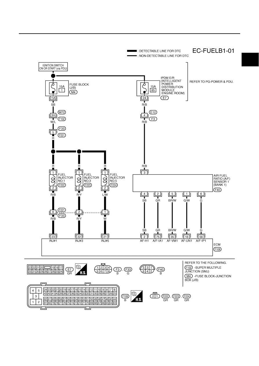
Wiring Diagram
NBS004XU
BANK 1
TBWT0956E
EC-312
[VQ35DE]
DTC P0171, P0174 FUEL INJECTION SYSTEM FUNCTION
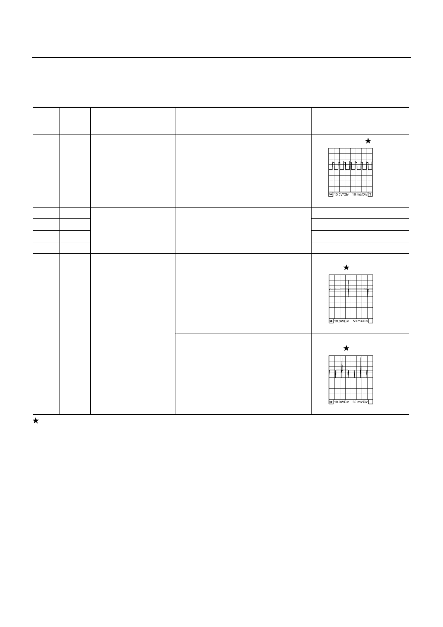
Specification data are reference values and are measured between each terminal and ground.
Pulse signal is measured by CONSULT-II.
CAUTION:
Do not use ECM ground terminals when measuring input/output voltage. Doing so may result in dam-
age to the ECMs transistor. Use a ground other than ECM terminals, such as the ground.
: Average voltage for pulse signal (Actual pulse signal can be confirmed by oscilloscope.)
TER-
MINAL
NO.
WIRE
COLOR
ITEM
CONDITION
DATA (DC Voltage)
2
SB
A/F sensor 1 heater
(bank 1)
[Engine is running]
●
Warm-up condition
●
Idle speed
Approximately 5V
16
G/W
A/F sensor 1 (bank 1)
[Engine is running]
●
Warm-up condition
●
Idle speed
Approximately 3.1V
35
BR/W
Approximately 2.6V
56
G
Approximately 2.3V
75
GR
Approximately 2.3V
21
22
23
W
R/Y
R/B
Fuel injector No. 5
Fuel injector No. 3
Fuel injector No. 1
[Engine is running]
●
Warm-up condition
●
Idle speed
NOTE:
The pulse cycle changes depending on rpm
at idle
BATTERY VOLTAGE
(11 - 14V)
[Engine is running]
●
Warm-up condition
●
Engine speed: 2,000 rpm
BATTERY VOLTAGE
(11 - 14V)
PBIB1584E
PBIB0042E
PBIB0043E
Нет комментариевНе стесняйтесь поделиться с нами вашим ценным мнением.
Текст