Infiniti M35/M45 Y50. Manual — part 208

TERMINALS AND REFERENCE VALUE FOR CONTROL UNIT
AV-209
[WITH MOBILE ENTERTAINMENT SYSTEM]
C
D
E
F
G
H
I
J
L
M
A
B
AV
*: With navigation system
54
(W/L)
Ground
Communication signal
(DISP-CONT)
Input
ON
When adjusting display
brightness.
55
–
Shield
–
–
–
–
61
(LG)
Ground
Illumination signal
Input
OFF
Lighting switch is OFF.
Approx. 0 V
Lighting switch is ON.
Approx. 12 V
63
(Y/G)
Ground
Ignition signal
Input
ON
–
Battery voltage
64
(P)
Ground
Parking brake signal
Input
ON
Parking brake ON.
Approx. 0 V
Parking brake OFF.
Approx. 12 V
65
(O)
Ground
Reverse signal
Input
ON
Select lever in R position.
Approx. 12 V
Other than selector lever in
R position.
Approx. 0 V
66
(G)
Ground
Vehicle speed signal
(8-pulse)
Input
ON
When vehicle speed is
approx. 40 km/h (25 MPH).
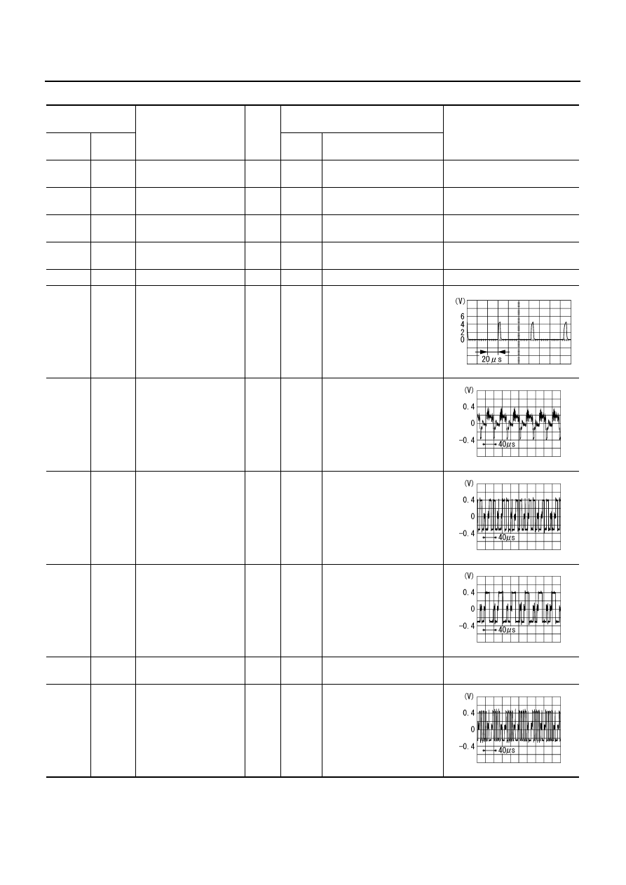
67
(V)
Ground
Camera-connection rec-
ognition signal
Input
ON
Connected to rear view
camera control unit connec-
tor.
Approx. 0 V
Not connected to rear view
camera control unit connec-
tor.
Approx. 5 V
69
(W)
–
Communication signal
(H)
Input/
Output
–
–
–
70
(R)
–
Communication signal
(L)
Input/
Output
–
–
–
71
(LG)
–
CAN-H
Input/
Output
–
–
–
72
(P)
–
CAN-L
Input/
Output
–
–
–
107
*
Ground
GPS signal
Input
ON
Connector is not connected.
Approx. 5 V
Terminal
(Wire color)
Item
Signal
Input/
output
Condition
Reference value
+
–
Ignition
switch
Operation
PKIB5039J
SKIA6649J
AV-210
[WITH MOBILE ENTERTAINMENT SYSTEM]
TERMINALS AND REFERENCE VALUE FOR CONTROL UNIT
Video Distributor
NKS004AP
Terminal
(Wire color)
Item
Signal
input/
output
Condition
Reference value
+
–
Ignition
Switch
Operation
1
(W)
–
Communication signal
(H)
Input/
Output
–
–
–
2
(R)
–
Communication signal
(L)
Input/
Output
–
–
–
3
(W)
–
Communication signal
(H)
Input/
Output
–
–
–
4
(O)
–
Communication signal
(L)
Input/
Output
–
–
–
6
–
Shield
–
–
–
–
7
(B/R)
Ground
Composite synchroniz-
ing signal (front)
Output
ON
Front display
DVD image
8
(BR)
Ground
Composite image signal
(front)
Output
ON
Front display
DVD image
10
(B)
12
(G)
RGB signal (R: red)
(front)
Output
ON
Start confirmation/adjust-
ment mode, and then dis-
play color bar by selecting
“Color Spectrum Bar” on
DISPLAY DIAGNOSIS
screen.
11
(W)
12
(G)
RGB signal (G: green)
(front)
Output
ON
Start confirmation/adjust-
ment mode, and then dis-
play color bar by selecting
“Color Spectrum Bar” on
DISPLAY DIAGNOSIS
screen.
12
(G)
–
RGB ground
–
ON
–
Approx. 0 V
13
(R)
12
(G)
RGB signal (B: blue)
(front)
Output
ON
Start confirmation/adjust-
ment mode, and then dis-
play color bar by selecting
“Color Spectrum Bar” on
DISPLAY DIAGNOSIS
screen.
SKIA0187E
SKIB2251J
SKIB2238J
SKIB2236J
SKIB2237J

TERMINALS AND REFERENCE VALUE FOR CONTROL UNIT
AV-211
[WITH MOBILE ENTERTAINMENT SYSTEM]
C
D
E
F
G
H
I
J
L
M
A
B
AV
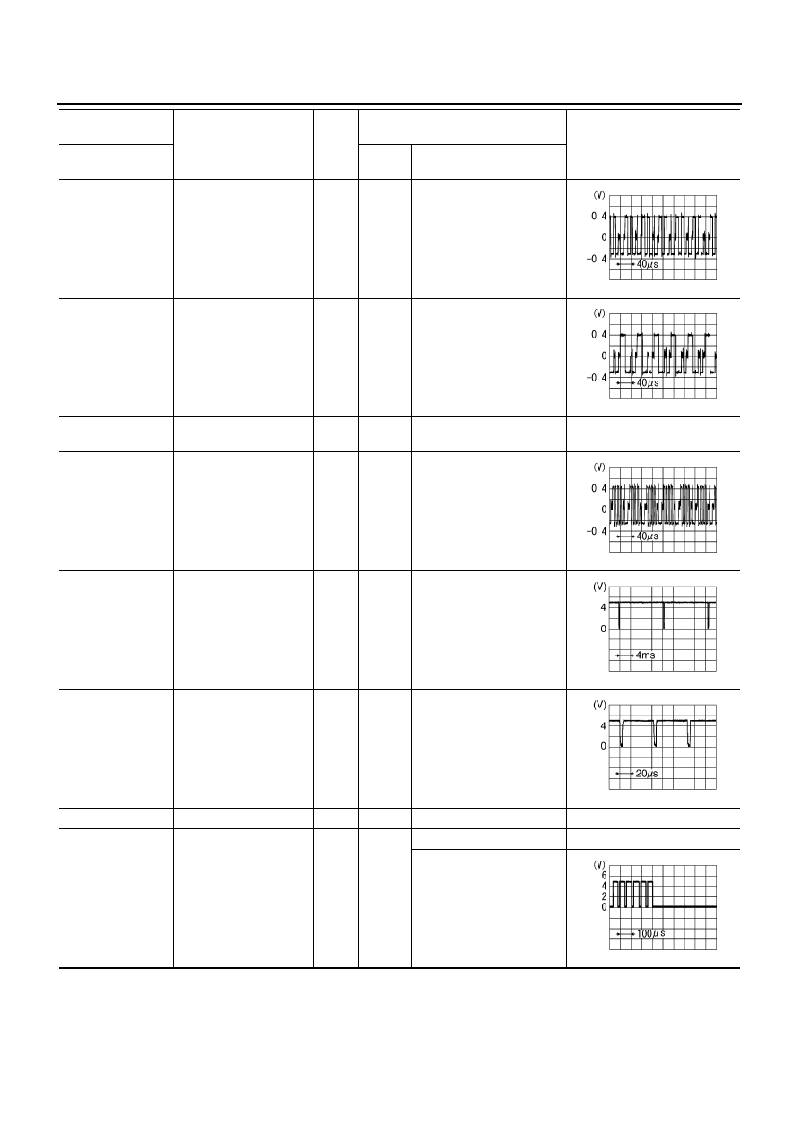
14
(L/G)
Ground
RGB area (YS) signal
(front)
Output
ON
When inputting RGB image.
Approx. 5 V
Set the selector lever in R
position, and then display
the rear view image.
15
(W/L)
Ground
Horizontal synchronizing
(HP) signal (front)
Input
ON
–
16
(O/L)
Ground
Vertical synchronizing
(VP) signal (front)
Input
ON
–
17
(L/Y)
Ground
RGB synchronizing
signal (front)
Output
ON
–
18
–
Shield
–
–
–
–
19
(R)
Ground
AUX image signal
Input
ON
AUX image
21
–
Shield
–
–
–
–
22
–
Shield
–
–
–
–
23
(L)
Ground
DVD image signal
Input
ON
DVD image
Terminal
(Wire color)
Item
Signal
input/
output
Condition
Reference value
+
–
Ignition
Switch
Operation
PKIB4948J
SKIB3601E
SKIB3598E
SKIA3222J
SKIB2251J
SKIB2251J
AV-212
[WITH MOBILE ENTERTAINMENT SYSTEM]
TERMINALS AND REFERENCE VALUE FOR CONTROL UNIT
25
(B)
27
(G)
RGB signal (R: red)
(rear)
Output
ON
Start confirmation/adjust-
ment mode, and then dis-
play color bar by selecting
“Color Spectrum Bar” on
DISPLAY DIAGNOSIS
screen.
26
(W)
27
(G)
RGB signal (G: green)
(rear)
Output
ON
Start confirmation/adjust-
ment mode, and then dis-
play color bar by selecting
“Color Spectrum Bar” on
DISPLAY DIAGNOSIS
screen.
27
(G)
Ground
RGB ground
–
ON
–
Approx. 0 V
28
(R)
27
(G)
RGB signal (B: blue)
(rear)
Output
ON
Start confirmation/adjust-
ment mode, and then dis-
play color bar by selecting
“Color Spectrum Bar” on
DISPLAY DIAGNOSIS
screen.
29
(W/R)
Ground
Vertical synchronizing
(VP) signal
(rear)
Input
ON
–
30
(W)
Ground
Horizontal synchronizing
(HP) signal (rear)
Input
ON
–
31
–
Shield
–
–
–
–
32
(R/L)
Ground
RGB area (YS) signal
(rear)
Output
ON
When inputting RGB image.
Approx. 5 V
Rear display
DVD image
Terminal
(Wire color)
Item
Signal
input/
output
Condition
Reference value
+
–
Ignition
Switch
Operation
SKIB2238J
SKIB2236J
SKIB2237J
SKIB0823E
SKIB0825E
PKIB4949J
Нет комментариевНе стесняйтесь поделиться с нами вашим ценным мнением.
Текст