Infiniti M35/M45 Y50. Manual — part 904
ACTIVE AFS
LT-161
C
D
E
F
G
H
I
J
L
M
A
B
LT
DTC B2503 SWIVEL ACTUATOR RH
NKS003QO
1.
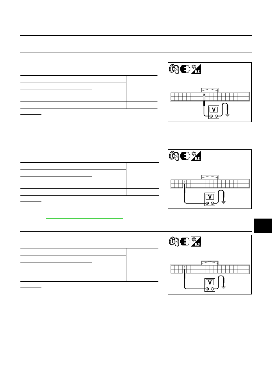
CHECK SWIVEL POSITION SENSOR SIGNAL
1.
Turn ignition switch ON.
2.
Check voltage between AFS control unit harness connector and
ground.
OK or NG
OK
>> GO TO 2.
NG
>>
●
If voltage is less than approx. 0.25V, GO TO 3.
●
If voltage is more than approx. 4.75V, GO TO 6.
2.
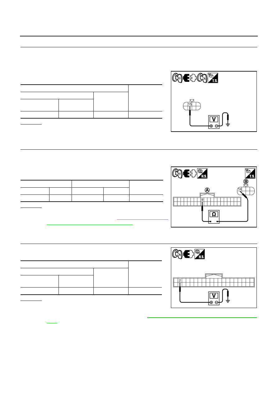
CHECK SWIVEL POSITION SENSOR POWER SUPPLY
Check voltage between AFS control unit harness connector and
ground.
OK or NG
OK
>> GO TO 12.
NG
>> Replace AFS control unit. Refer to
and Installation of AFS Control Unit"
3.
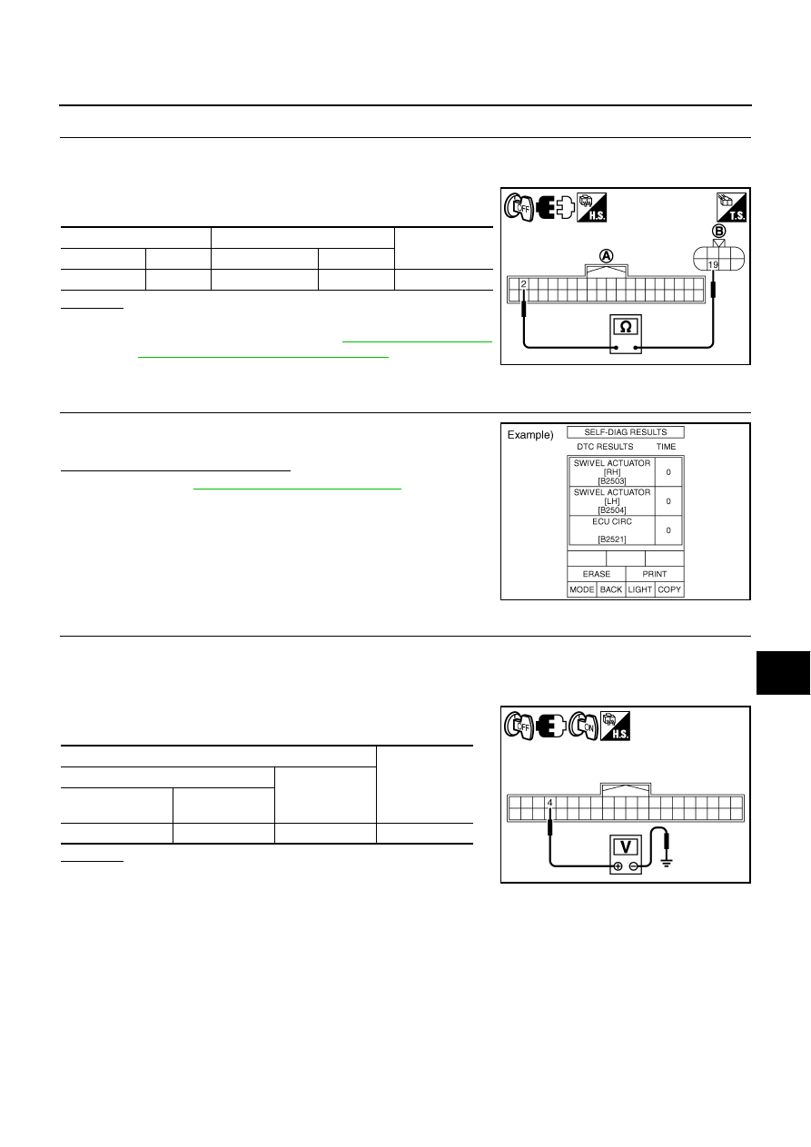
CHECK SWIVEL POSITION SENSOR POWER SUPPLY
Check voltage between AFS control unit harness connector and
ground.
OK or NG
OK
>> GO TO 4.
NG
>> GO TO 8.
Terminals
Voltage
(Approx.)
(+)
(-)
AFS control unit
connector
Terminal
F110
9
Ground
0.25 - 4.75 V
PKIC0646E
Terminals
Voltage
(Approx.)
(+)
(-)
AFS control unit
connector
Terminal
F110
4
Ground
4.0 - 6.0 V
PKIC0645E
Terminals
Voltage
(Approx.)
(+)
(-)
AFS control unit
connector
Terminal
F110
4
Ground
4.0 - 6.0 V
PKIC0645E
LT-162
ACTIVE AFS
4.
CHECK SWIVEL POSITION SENSOR POWER SUPPLY CIRCUIT
1.
Turn ignition switch OFF.
2.
Disconnect front combination lamp RH connector.
3.
Turn ignition switch ON.
4.
Check voltage between front combination lamp RH harness
connector and ground.
OK or NG
OK
>> GO TO 5.
NG
>> Repair harness or connector.
5.
CHECK SWIVEL POSITION SENSOR SIGNAL CIRCUIT
1.
Turn ignition switch OFF.
2.
Disconnect AFS control unit connector.
3.
Check continuity between AFS control unit harness connector
(A) and front combination lamp RH harness connector (B).
OK or NG
OK
>> Replace front combination lamp RH (swivel position
Installation of Front Combination Lamp"
NG
>> Repair harness or connector.
6.
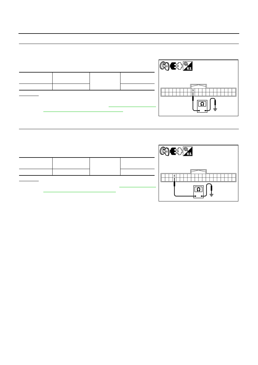
CHECK SWIVEL POSITION SENSOR GROUND
Check voltage between AFS control unit harness connector and
ground.
OK or NG
OK
>> GO TO 7.
NG
>> Check connector for connection, bend and loose fit. If it
is normal, replace AFS control unit. Refer to
LT-192, "Removal and Installation of AFS Control
Terminals
Voltage
(Approx.)
(+)
(-)
Front combination
lamp RH connector
Terminal
E48
15
Ground
4.0 - 6.0 V
PKIC0647E
A
B
Continuity
Connector
Terminal Connector
Terminal
F110
9
E48
14
Yes
PKIC0648E
Terminals
Voltage
(Approx.)
(+)
(-)
AFS control unit
connector
Terminal
F110
2
Ground
0 V
PKIC0649E
ACTIVE AFS
LT-163
C
D
E
F
G
H
I
J
L
M
A
B
LT
7.
CHECK SWIVEL POSITION SENSOR GROUND CIRCUIT
1.
Turn ignition switch OFF.
2.
Disconnect AFS control unit connector and front combination lamp RH connector.
3.
Check continuity between AFS control unit harness connector
(A) and front combination lamp RH harness connector (B).
OK or NG
OK
>> Replace front combination lamp RH (swivel position
sensor malfunction). Refer to
Installation of Front Combination Lamp"
NG
>> Repair harness or connector.
8.
CHECK DIAGNOSIS RESULT
Select “ADAPTIVE LIGHT” on CONSULT-II. Select “SELF-DIAG
RESULTS” on “SELECT DIAG MODE” screen.
Is DTC B2521 ECU CIRC detected?
YES
>> Refer to
NO
>> GO TO 9.
9.
CHECK SWIVEL POSITION SENSOR POWER SUPPLY CIRCUIT
1.
Turn ignition switch OFF.
2.
Disconnect front combination lamp RH connector.
3.
Turn ignition switch ON.
4.
Check voltage between AFS control unit harness connector and
ground.
OK or NG
OK
>> GO TO 10.
NG
>> GO TO 11.
A
B
Continuity
Connector
Terminal Connector
Terminal
F110
2
E48
19
Yes
PKIC0650E
SKIB4975E
Terminals
Voltage
(Approx.)
(+)
(-)
AFS control unit
connector
Terminal
F110
4
Ground
4.0 - 6.0 V
PKIC0651E
LT-164
ACTIVE AFS
10.
CHECK SWIVEL POSITION SENSOR SIGNAL CIRCUIT (SHORT CIRCUIT)
1.
Turn ignition switch OFF.
2.
Disconnect AFS control unit connector.
3.
Check continuity between AFS control unit harness connector
and ground.
OK or NG
OK
>> Replace front combination lamp RH (swivel position
Installation of Front Combination Lamp"
NG
>> Repair harness or connector.
11.
CHECK SWIVEL POSITION SENSOR POWER SUPPLY CIRCUIT (SHORT CIRCUIT)
1.
Turn ignition switch OFF.
2.
Disconnect AFS control unit connector.
3.
Check continuity between AFS control unit harness connector
and ground.
OK or NG
OK
>> Replace AFS control unit. Refer to
and Installation of AFS Control Unit"
.
NG
>> Repair harness or connector.
AFS control unit
connector
Terminal
Ground
Continuity
F110
9
No
SKIB4968E
AFS control unit
connector
Terminal
Ground
Continuity
F110
4
No
PKIC0652E
Нет комментариевНе стесняйтесь поделиться с нами вашим ценным мнением.
Текст