Infiniti M35/M45 Y50. Manual — part 466
DTC P0182, P0183 FTT SENSOR
EC-337
[VQ35DE]
C
D
E
F
G
H
I
J
K
L
M
A
EC
DTC P0182, P0183 FTT SENSOR
PFP:22630
Component Description
NBS004Y7
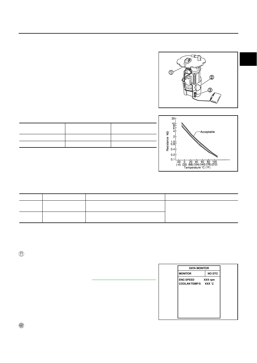
The fuel tank temperature sensor (3) is used to detect the fuel tem-
perature inside the fuel tank. The sensor modifies a voltage signal
from the ECM. The modified signal returns to the ECM as the fuel
temperature input. The sensor uses a thermistor which is sensitive to
the change in temperature. The electrical resistance of the ther-
mistor decreases as temperature increases.
●
Fuel level sensor unit and fuel pump (1)
●
Fuel pressure regulator (2)
<Reference data>
*: This data is reference value and is measured between ECM terminal 107 (Fuel
tank temperature sensor) and ground.
CAUTION:
Do not use ECM ground terminals when measuring input/output
voltage. Doing so may result in damage to the ECM's transistor.
Use a ground other than ECM terminals, such as the ground.
On Board Diagnosis Logic
NBS004Y8
DTC Confirmation Procedure
NBS004Y9
NOTE:
If DTC Confirmation Procedure has been previously conducted, always turn ignition switch OFF and wait at
least 10 seconds before conducting the next test.
WITH CONSULT-II
1.
Turn ignition switch ON.
2.
Select “DATA MONITOR” mode with CONSULT-II.
3.
Wait at least 5 seconds.
4.
If 1st trip DTC is detected, go to
EC-339, "Diagnostic Procedure"
.
WITH GST
Follow the procedure “WITH CONSULT-II” above.
PBIB2707E
Fluid temperature
°
C (
°
F)
Voltage*
V
Resistance
k
Ω
20 (68)
3.5
2.3 - 2.7
50 (122)
2.2
0.79 - 0.90
SEF012P
DTC No.
Trouble diagnosis name
DTC detecting condition
Possible cause
P0182
0182
Fuel tank temperature
sensor circuit low input
An excessively low voltage from the sensor is
sent to ECM.
●
Harness or connectors
(The sensor circuit is open or shorted.)
●
Fuel tank temperature sensor
P0183
0183
Fuel tank temperature
sensor circuit high input
An excessively high voltage from the sensor is
sent to ECM.
SEF174Y
EC-338
[VQ35DE]
DTC P0182, P0183 FTT SENSOR
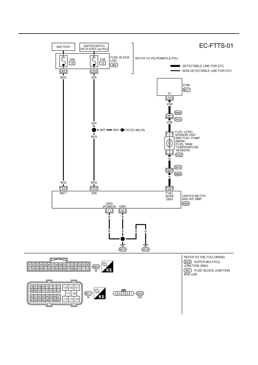
Wiring Diagram
NBS004YA
TBWT1531E
DTC P0182, P0183 FTT SENSOR
EC-339
[VQ35DE]
C
D
E
F
G
H
I
J
K
L
M
A
EC
Diagnostic Procedure
NBS004YB
1.
CHECK GROUND CONNECTIONS
1.
Turn ignition switch OFF.
2.
Loosen and retighten two ground screws on the body.
Refer to
OK or NG
OK
>> GO TO 2.
NG
>> Repair or replace ground connections.
2.
CHECK DTC WITH “UNIFIED METER AND A/C AMP.”
Refer to
OK or NG
OK
>> GO TO 3.
NG
DI-22, "Fuel Level Sensor Signal Inspection"
.
3.
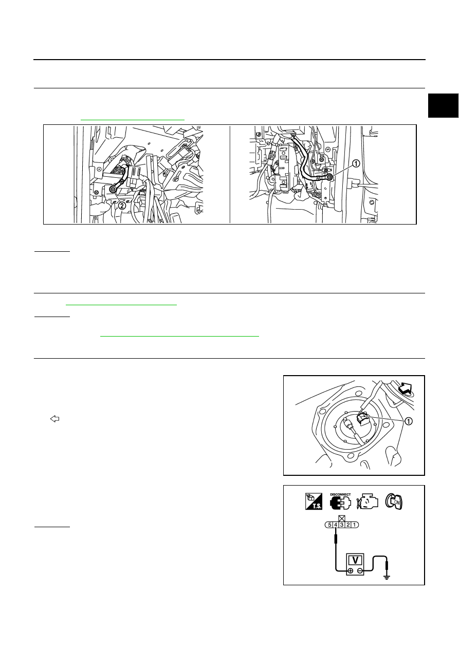
CHECK FUEL TANK TEMPERATURE SENSOR POWER SUPPLY CIRCUIT
1.
Turn ignition switch OFF.
2.
Disconnect “fuel level sensor unit and fuel pump” harness con-
nector (1).
–
Illustration shows the view with rear seat cushion and inspection
hole cover (RH) removed.
–
: Vehicle front
3.
Turn ignition switch ON.
4.
Check voltage between “fuel level sensor unit and fuel pump”
terminal 4 and ground with CONSULT-II or tester.
OK or NG
OK
>> GO TO 5.
NG
>> GO TO 4.
1.
Body ground M70
2.
Body ground M16
PBIB2782E
PBIB2706E
Voltage: Approximately 5V
PBIB0932E
EC-340
[VQ35DE]
DTC P0182, P0183 FTT SENSOR
4.
DETECT MALFUNCTIONING PART
Check the following.
●
Harness connectors M66, B418
●
Harness for open or short between ECM and “fuel level sensor unit and fuel pump”
>> Repair open circuit or short to ground or short to power in harness or connector.
5.
CHECK FUEL TANK TEMPERATURE SENSOR GROUND CIRCUIT FOR OPEN AND SHORT
1.
Turn ignition switch OFF.
2.
Disconnect “unified meter and A/C amp.” harness connector.
3.
Check harness continuity between “fuel level sensor unit and fuel pump” terminal 5 and “unified meter and
A/C amp.” terminal 58. Refer to Wiring Diagram.
4.
Also check harness for short to ground and short to power.
OK or NG
OK
>> GO TO 7.
NG
>> GO TO 6.
6.
DETECT MALFUNCTIONING PART
Check the following.
●
Harness connectors M66, B418
●
Harness for open or short between “fuel level sensor unit and fuel pump” and “unified meter and A/C
amp.”
>> Repair open circuit or short to ground or short to power in harness or connector.
7.
CHECK FUEL TANK TEMPERATURE SENSOR
Refer to
EC-341, "Component Inspection"
OK or NG
OK
>> GO TO 8.
NG
>> Replace “fuel level sensor unit and fuel pump”.
8.
CHECK INTERMITTENT INCIDENT
Refer to
EC-153, "TROUBLE DIAGNOSIS FOR INTERMITTENT INCIDENT"
.
>> INSPECTION END
Continuity should exist.
Нет комментариевНе стесняйтесь поделиться с нами вашим ценным мнением.
Текст