Infiniti M35/M45 Y50. Manual — part 892
HEADLAMP (FOR CANADA) - DAYTIME LIGHT SYSTEM -
LT-113
C
D
E
F
G
H
I
J
L
M
A
B
LT
Headlamps Do Not Turn OFF
NKS003PQ
1.
CHECK HEADLAMP TURN OFF
Make sure that lighting switch is OFF. And make sure is headlamp turns off when ignition switch is turned OFF.
OK or NG
OK
>> GO TO 3.
NG
>> GO TO 2.
2.
CHECK COMBINATION SWITCH INPUT SIGNAL
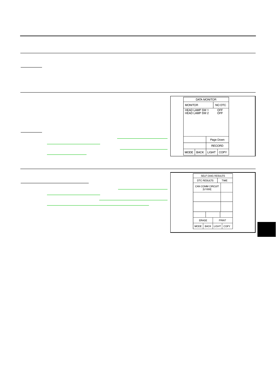
Select “BCM” on CONSULT-II. With “HEAD LAMP” data monitor,
make sure “HEAD LAMP SW 1” and “HEAD LAMP SW 2” turns ON-
OFF linked with operation of lighting switch.
OK or NG
OK
>> Replace IPDM E/R. Refer to
.
NG
>> Check lighting switch. Refer to
3.
CHECK CAN COMMUNICATIONS BETWEEN BCM AND IPDM E/R
Select “BCM” by CONSULT-II, and perform self-diagnosis for “BCM”.
Display of self-diagnosis results
NO DTC>> Replace IPDM E/R. Refer to
.
CAN COMM CIRCUIT>> Refer to
Inspection Using CONSULT-II (Self-Diagnosis)"
When lighting switch is OFF
position
: HEAD LAMP SW 1 OFF
: HEAD LAMP SW 2 OFF
PKIA7011E
PKIA7627E

LT-114
HEADLAMP (FOR CANADA) - DAYTIME LIGHT SYSTEM -
General Information for Xenon Headlamp Trouble Diagnosis
NKS003PR
In most cases, malfunction of xenon headlamp - “does not illuminate”, “flickers” or “dark” - is caused by a mal-
functioning xenon bulb. A HID control unit or lamp housing, however, may be a cause of malfunction. Be sure
to perform trouble diagnosis following the steps described below.
CAUTION:
NKS003PS
●
Installation or removal of connector must be done with lighting switch OFF.
●
When lamp is illuminated (when lighting switch is ON), do not touch harness, HID control unit, inside of
lamp, or lamp metal parts.
●
To check illumination, temporarily install lamp in the vehicle. Be sure to connect power at the vehicle-side
connector.
●
If the error can be traced directly to the electrical system, first check for items such as burned-out fuses
and fusible links, broken wires or loose connectors, pulled-out terminals, and improper connections.
●
Do not work with wet hands.
●
Using a tester for HID control unit circuit trouble diagnosis is prohibited.
●
Disassembling the HID control unit or harnesses (bulb socket harness, ECM harness) is prohibited.
●
Immediately after illumination, the light intensity and color will fluctuate, but there is nothing wrong.
●
When the bulb has reached the end of its lifetime, the brightness may drop significantly, it may flash
repeatedly, or the light may turn a reddish color.
Xenon Headlamp Trouble Diagnosis
NKS003PT
1.
CHECK 1: XENON HEADLAMP LIGHTING
Install normal xenon bulb to corresponding xenon bulb headlamp, and check if lamp lights up.
OK or NG
OK
>> Replace xenon bulb.
NG
>> GO TO 2.
2.
CHECK 2: XENON HEADLAMP LIGHTING
Install normal HID control unit to corresponding xenon headlamp, and check if lamp lights up.
OK or NG
OK
>> Replace HID control unit.
NG
>> GO TO 3.
3.
CHECK 3: XENON HEADLAMP LIGHTING
Install normal xenon lamp housing assembly to corresponding xenon headlamp, and check if lamp lights up.
OK or NG
OK
>> Replace xenon headlamp housing assembly.
NG
>> INSPECTION END
Aiming Adjustment
NKS003PU
Refer to
.
Bulb Replacement
NKS003PV
Refer to
Removal and Installation
NKS003PW
Refer to
LT-75, "Removal and Installation"
.
Disassembly and Assembly
NKS003PX
Refer to
AUTO LIGHT SYSTEM
LT-115
C
D
E
F
G
H
I
J
L
M
A
B
LT
AUTO LIGHT SYSTEM
PFP:28491
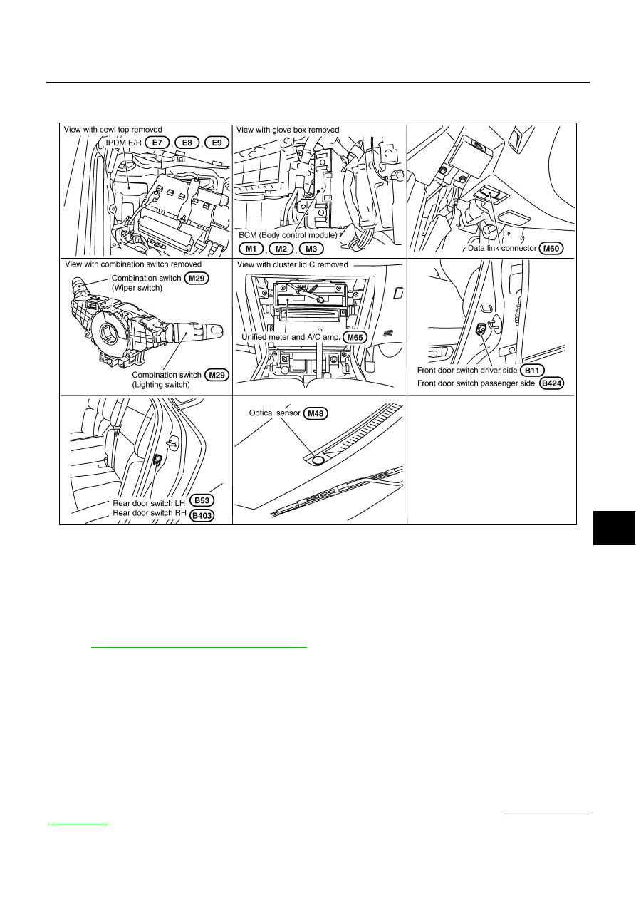
Component Parts and Harness Connector Location
NKS003PY
System Description
NKS003PZ
Automatically turns ON/OFF the parking lamps and the headlamps in accordance with ambient light.
Timing for when lamps turn ON/OFF can be selected using four modes.
OUTLINE
The auto light control system has an optical sensor inside it that detects outside brightness.
When the lighting switch is in AUTO position, it automatically turns ON/OFF the parking lamps and the head-
lamps in accordance with ambient light. Sensitivity can be adjusted in four steps. For the details of the setting,
Refer to
LT-127, "SETTING CHANGE FUNCTIONS"
Optical sensor, power is supplied
●
from BCM (body control module) terminal 17
●
to optical sensor terminal 1.
Optical sensor, ground is supplied
●
to optical sensor terminal 3
●
through BCM terminal 18.
When ignition switch is turn to ON position, and
When outside brightness is darker than prescribed level, input is supplied
●
from optical sensor terminal 2
●
to BCM terminal 14.
The headlamps will then illuminate. For a description of headlamp operation, Refer to
PKID0501E

LT-116
AUTO LIGHT SYSTEM
COMBINATION SWITCH READING FUNCTION
Refer to
BCS-3, "COMBINATION SWITCH READING FUNCTION"
EXTERIOR LAMP BATTERY SAVER CONTROL
When the combination switch (lighting switch) is in the 2ND position (or if auto light system is activated), and
the ignition switch is turned from ON or ACC to OFF, the battery saver control function is activated.
Under this condition, the headlamps remain illuminated for 5 minutes, then the headlamps are turned off.
Exterior lamp battery saver control mode can be changed by the function setting of CONSULT-II.
DELAY TIMER FUNCTION
Delay timer function carries out a function that BCM activates the timer and controls lights out of headlamps by
door switch signal and lightning switch signal when turning the Ignition switch OFF while it is ON and head-
lamps are ON by the auto light function.
Timer types are a 5 minutes timer and a 45 seconds timer
●
When opening any door (door switch is ON), the 5 minutes timer starts and then headlamps go out five
minutes later
●
When all the doors are closed (from door switch ON to OFF), the 45 second timer starts and then head-
lamps go out 45 seconds later. If any door is opened (door switch ON) while the 45 seconds timer is in
operation, the 5 minutes timer starts again
●
The timer stops when turning on the ignition switch or turning off the auto light switch under the above
conditions.
Delay timer control mode can be changed by the function setting of CONSULT-II.
CAN Communication System Description
NKS003Q0
CAN (Controller Area Network) is a serial communication line for real time application. It is an on-vehicle mul-
tiplex communication line with high data communication speed and excellent error detection ability. Many elec-
tronic control units are equipped onto vehicle, and each control unit shares information and links with other
control units during operation (not independent). In CAN communication, control units are connected with 2
communication lines (CAN H line, CAN L line) allowing the high rate of information transmission with less wir-
ing. Each control unit transmits/receives data but selectively reads required data only.
CAN Communication Unit
NKS003Q1
Refer to
LAN-50, "CAN System Specification Chart"
Major Components and Functions
NKS003Q2
Components
Functions
BCM
●
Turns on/off circuits of tail light and headlamp according to signals from optical sensor, lighting switch
(AUTO), driver door switch, passenger door switch, rear door switch, and ignition switch (ON, OFF).
Optical sensor
●
Converts outside brightness (lux) to voltage, and sends it to BCM. (Detects brightness of 50 to 1,300 lux)
Нет комментариевНе стесняйтесь поделиться с нами вашим ценным мнением.
Текст