Infiniti M35/M45 Y50. Manual — part 472
DTC P0327, P0328 KS
EC-361
[VQ35DE]
C
D
E
F
G
H
I
J
K
L
M
A
EC
Specification data are reference values and are measured between each terminal and ground.
CAUTION:
Do not use ECM ground terminals when measuring input/output voltage. Doing so may result in dam-
age to the ECM's transistor. Use a ground other than ECM terminals, such as the ground.
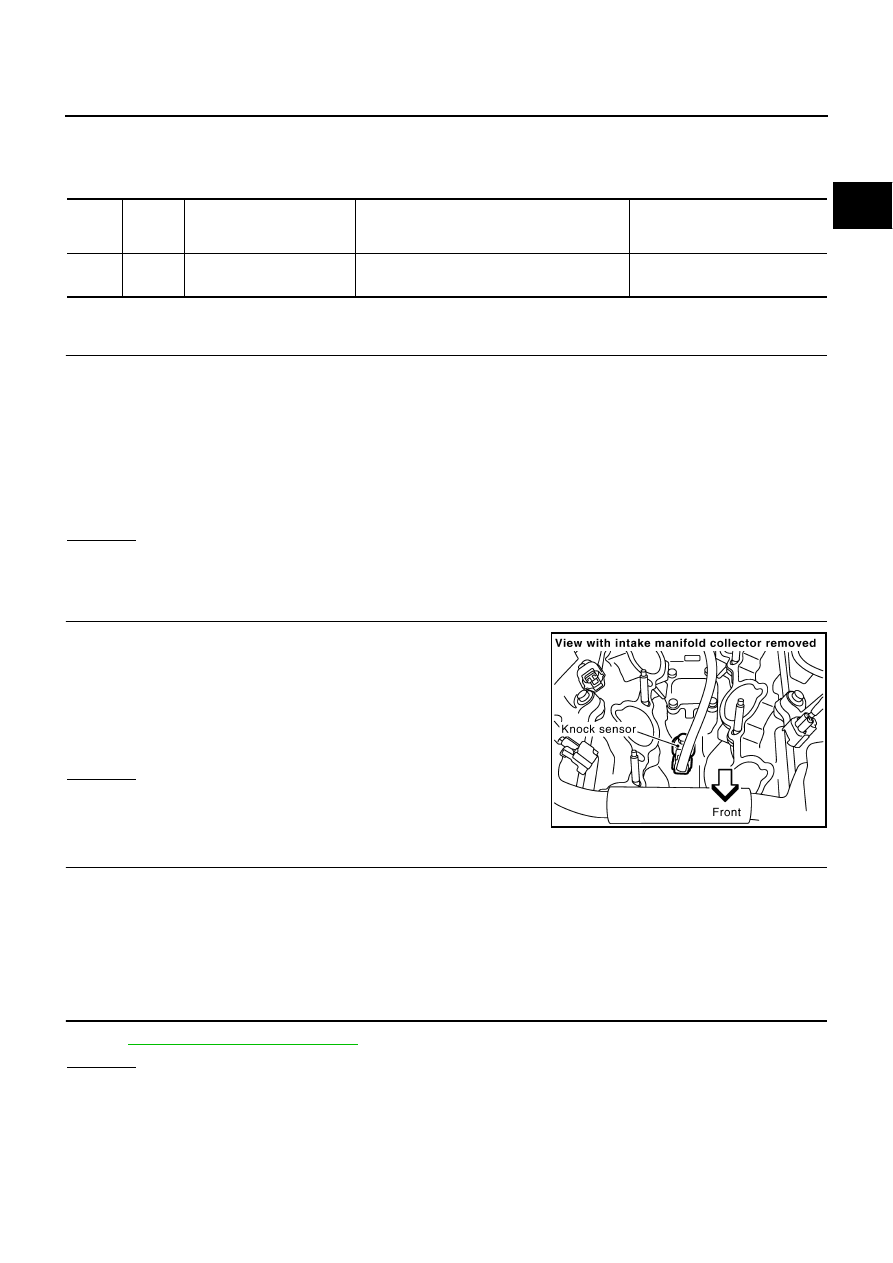
Diagnostic Procedure
NBS004YT
1.
CHECK KNOCK SENSOR INPUT SIGNAL CIRCUIT FOR OPEN AND SHORT-I
1.
Turn ignition switch OFF.
2.
Disconnect ECM harness connector.
3.
Check resistance between ECM terminal 15 and ground. Refer to Wiring Diagram.
NOTE:
It is necessary to use an ohmmeter which can measure more than 10 M
Ω
.
4.
Also check harness for short to ground and short to power.
OK or NG
OK
>> GO TO 5.
NG
>> GO TO 2.
2.
CHECK KNOCK SENSOR INPUT SIGNAL CIRCUIT FOR OPEN AND SHORT-II
1.
Disconnect knock sensor harness connector.
2.
Check harness continuity between ECM terminal 15 and knock
sensor terminal 1.
Refer to Wiring Diagram.
3.
Also check harness for short to ground and short to power.
OK or NG
OK
>> GO TO 4.
NG
>> GO TO 3.
3.
DETECT MALFUNCTIONING PART
Check the following.
●
Harness connectors F37, F229
●
Harness for open or short between ECM and knock sensor
>> Repair open circuit or short to ground or short to power in harness or connectors.
4.
CHECK KNOCK SENSOR
Refer to
EC-363, "Component Inspection"
OK or NG
OK
>> GO TO 5.
NG
>> Replace knock sensor.
TER-
MINAL
NO.
WIRE
COLOR
ITEM
CONDITION
DATA (DC Voltage)
15
W
Knock sensor
[Engine is running]
●
Idle speed
Approximately 2.5V
Resistance: Approximately 532 - 588 k
Ω
[at 20
°
C (68
°
F)]
Continuity should exist.
PBIB1564E
EC-362
[VQ35DE]
DTC P0327, P0328 KS
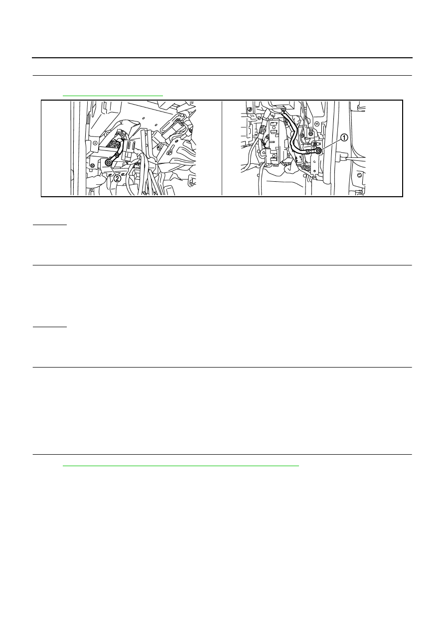
5.
CHECK GROUND CONNECTIONS
Loosen and retighten two ground screws on the body.
Refer to
.
OK or NG
OK
>> GO TO 6.
NG
>> Repair or replace ground connections.
6.
CHECK KNOCK SENSOR SHIELD CIRCUIT FOR OPEN AND SHORT
1.
Disconnect knock sensor harness connector.
2.
Check harness continuity between knock sensor terminal 2 and ground. Refer to Wiring Diagram.
3.
Also check harness for short to power.
OK or NG
OK
>> GO TO 8.
NG
>> GO TO 7.
7.
DETECT MALFUNCTIONING PART
Check the following.
●
Harness connectors F37, F229
●
Harness connectors F102, M72
●
Harness for open or short between knock sensor terminal 2 and ground
>> Repair open circuit or short to power in harness or connectors.
8.
CHECK INTERMITTENT INCIDENT
Refer to
EC-153, "TROUBLE DIAGNOSIS FOR INTERMITTENT INCIDENT"
.
>> INSPECTION END
1.
Body ground M70
2.
Body ground M16
PBIB2782E
Continuity should exist.
DTC P0327, P0328 KS
EC-363
[VQ35DE]
C
D
E
F
G
H
I
J
K
L
M
A
EC
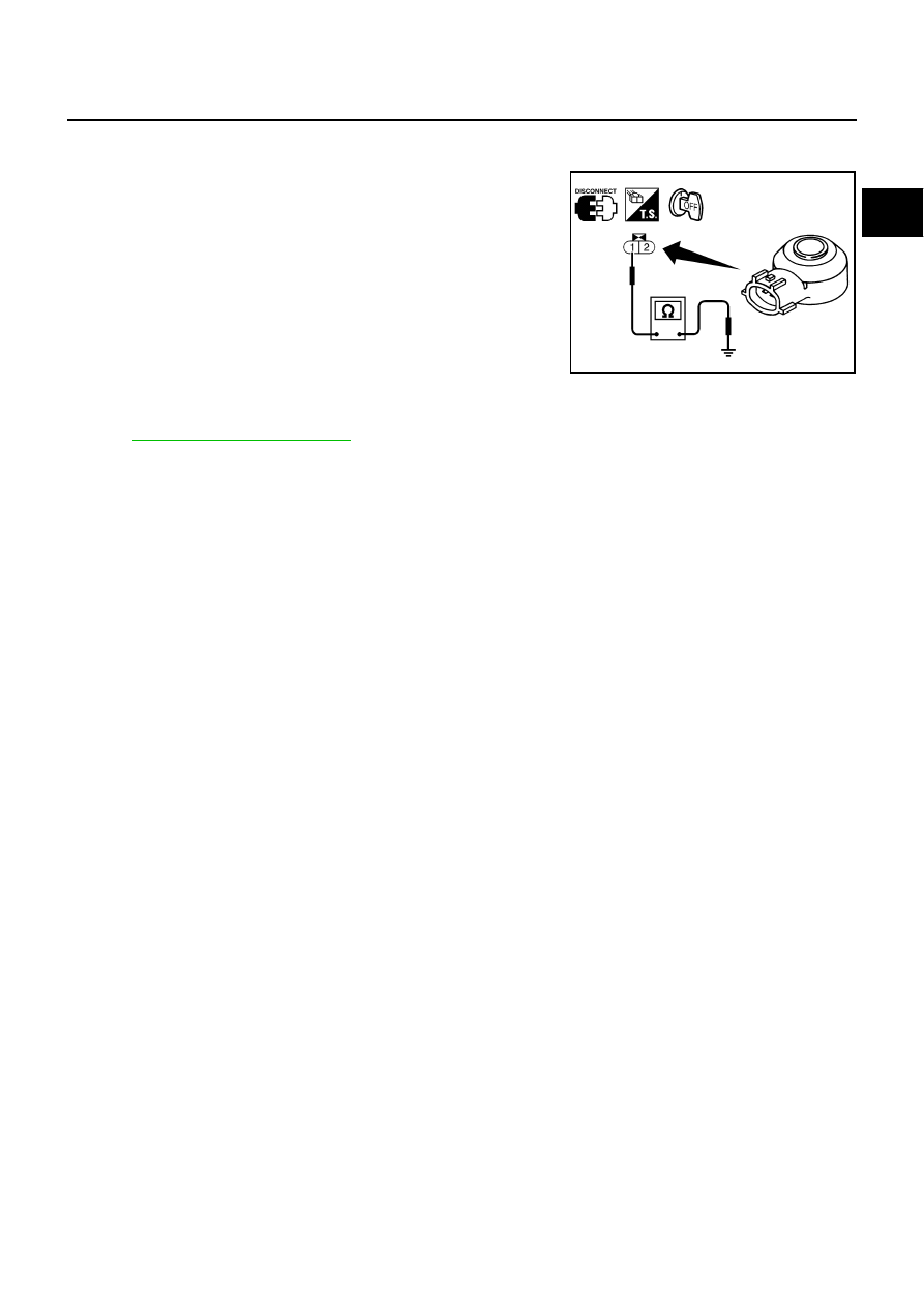
Component Inspection
NBS004YU
KNOCK SENSOR
Check resistance between knock sensor terminal 1 and ground.
NOTE:
It is necessary to use an ohmmeter which can measure more
than 10 M
Ω
.
CAUTION:
Do not use any knock sensors that have been dropped or phys-
ically damaged. Use only new ones.
Removal and Installation
NBS004YV
KNOCK SENSOR
Refer to
.
Resistance: Approximately 532 - 588 k
Ω
[at 20
°
C (68
°
F)]
SEF111Y
EC-364
[VQ35DE]
DTC P0335 CKP SENSOR (POS)
DTC P0335 CKP SENSOR (POS)
PFP:23731
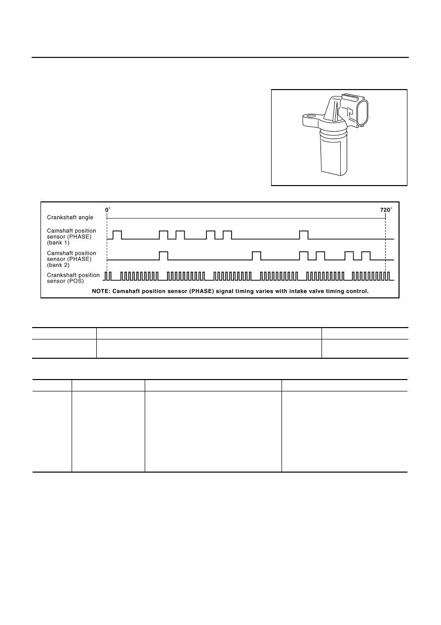
Component Description
NBS004YW
The crankshaft position sensor (POS) is located on the oil pan facing
the gear teeth (cogs) of the signal plate. It detects the fluctuation of
the engine revolution.
The sensor consists of a permanent magnet and Hall IC.
When the engine is running, the high and low parts of the teeth
cause the gap with the sensor to change.
The changing gap causes the magnetic field near the sensor to
change.
Due to the changing magnetic field, the voltage from the sensor
changes.
The ECM receives the voltage signal and detects the fluctuation of
the engine revolution.
ECM receives the signals as shown in the figure.
CONSULT-II Reference Value in Data Monitor Mode
NBS004YX
Specification data are reference values.
On Board Diagnosis Logic
NBS004YY
PBIB0562E
PBIB2744E
MONITOR ITEM
CONDITION
SPECIFICATION
ENG SPEED
●
Run engine and compare CONSULT-II value with the tachometer indication.
Almost the same speed as
the tachometer indication.
DTC No.
Trouble diagnosis name
DTC detecting condition
Possible cause
P0335
0335
Crankshaft position
sensor (POS) circuit
●
The crankshaft position sensor (POS) signal
is not detected by the ECM during the first
few seconds of engine cranking.
●
The proper pulse signal from the crankshaft
position sensor (POS) is not sent to ECM
while the engine is running.
●
The crankshaft position sensor (POS) signal
is not in the normal pattern during engine
running.
●
Harness or connectors
(The sensor circuit is open or shorted)
●
Crankshaft position sensor (POS)
●
Signal plate
Нет комментариевНе стесняйтесь поделиться с нами вашим ценным мнением.
Текст