Infiniti M35/M45 Y50. Manual — part 276
INTELLIGENT KEY SYSTEM/ENGINE START FUNCTION
BL-173
C
D
E
F
G
H
J
K
L
M
A
B
BL
TERMINALS AND REFERENCE VALUE
Intelligent Key Unit
PDU (Power Distribution Unit)
SELF-DIAGNOSTIC LOGIC
DIAGNOSTIC PROCEDURE
1.
CHECK HARNESS CONTINUITY 1
1.
Turn ignition switch OFF.
2.
Disconnect Intelligent Key unit and power distribution unit connector.
3.
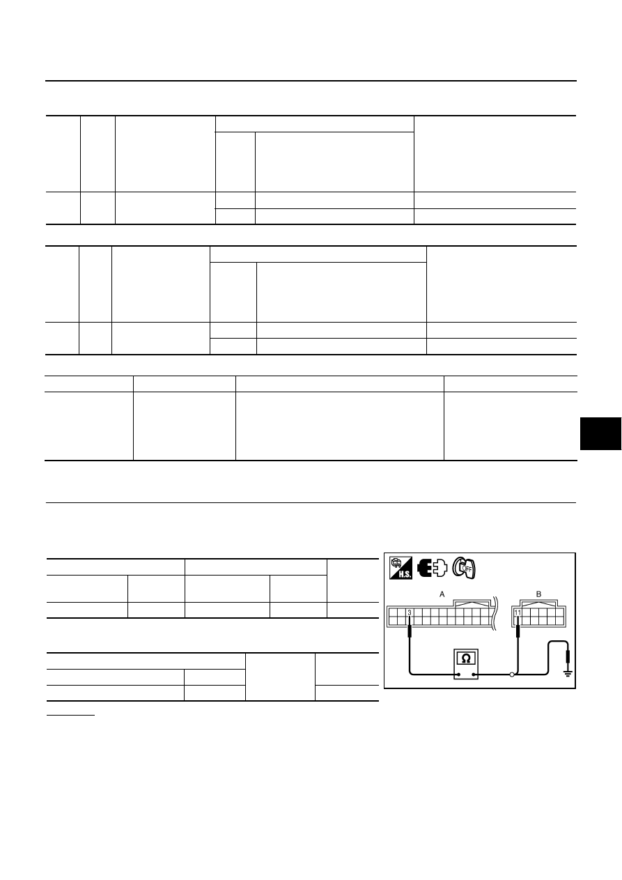
Check continuity between Intelligent Key unit connector and power distribution unit connector.
4.
Check continuity between Intelligent Key unit connector and
ground.
OK or NG
OK
>> GO TO 2.
NG
>> Repair or replace harness.
Termi-
nal
No.
Wire
color
Item
Condition
Voltage (V)
(Approx.)
Push-
button
ignition
switch
position
Operation or conditions
3
Y
IPDM E/R current sig-
nal
START
At starter motor cranking
5
LOCK
Any condition other than above
2
Ter-
minal
No.
Wire
color
Item
Condition
Voltage (V)
(Approx.)
Push-
button
ignition
switch
position
Operation or conditions
13
R
Starter relay
START
At starter motor cranking
Battery voltage
—
Any condition other than above
4
DTC
Self-diagnosis name
DTC detecting condition
Possible causes
B2560
START POW SUP
CIRC
It is detected that the power is supplied to the
starter motor without the engine start request from
the Intelligent Key unit
●
Harness and connector
(Open in the circuit between
the units)
●
PDU
●
IPDM E/R
A
B
Continuity
Intelligent Key
unit connector
Terminal
Power distribution
unit connector
Terminal
M32
3
M30
11
Yes
A
Ground
Continuity
Intelligent Key unit connector
Terminal
M32
3
No
PIIB6249E
BL-174
INTELLIGENT KEY SYSTEM/ENGINE START FUNCTION
2.
CHECK HARNESS CONTINUITY 2
1.
Disconnect IPDM E/R connector.
2.
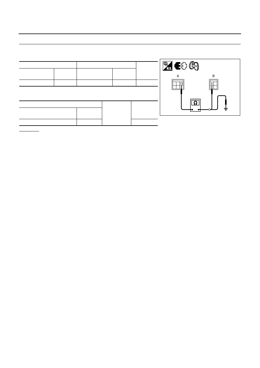
Check continuity between power distribution unit connector and IPDM E/R connector.
3.
Check continuity between power distribution unit connector and
ground.
OK or NG
OK
>> Replace IPDM E/R.
NG
>> Repair or replace harness.
A
B
Continuity
Power distribution
unit connector
Terminal
IPDM E/R
connector
Terminal
M31
13
E4
4
Yes
A
Ground
Continuity
Power distribution unit
connector
Terminal
M31
13
No
PIIB6250E

INTELLIGENT KEY SYSTEM/ENGINE START FUNCTION
BL-175
C
D
E
F
G
H
J
K
L
M
A
B
BL
DTC B2562 LOW VOLTAGE
NIS001YY
DIAGNOSIS DESCRIPTION
B2562 battery low voltage monitors the battery voltage input to Intelligent Key unit. When the condition that the
voltage is 8.8V or less is detected for 1.5 seconds or more, it judges that it is the malfunction and displays the
DTC (Diagnostic Trouble Code)
TERMINALS AND REFERENCE VALUE FOR INTELLIGENT KEY UNIT
Standard is the measured voltage between each terminal and ground
SELF-DIAGNOSTIC LOGIC
DIAGNOSTIC PROCEDURE
1.
CHECK BATTERY
Measure the battery output voltage. Make sure that it is 9V or more.
OK or NG
OK
>> GO TO 2.
NG
>> Charge or replace the battery.
Termi-
nal
No.
Wire
color
Item
Condition
Voltage (V)
(Approx.)
Push-
button
ignition
switch
position
Operation or conditions
1
SB
Power source (fuse)
—
—
Battery voltage
41
Y
Power source (fuse)
—
—
Battery voltage
57
L
Power source (fuse)
—
—
Battery voltage
DTC
Self-diagnosis name
DTC detecting condition
Possible causes
B2562
LOW VOLTAGE
It is detected for 1.5 seconds or more that the battery volt-
age that is input to the Intelligent Key unit is 8.8V or less
●
Fuse
●
Harness and connector
(Open in the circuit)
BL-176
INTELLIGENT KEY SYSTEM/ENGINE START FUNCTION
2.
CHECK POWER SUPPLY CIRCUIT
1.
Turn ignition switch OFF.
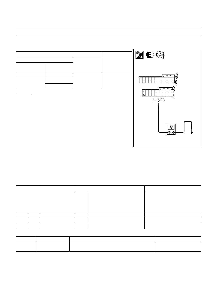
2.
Check voltage between Intelligent Key unit connector and ground.
OK or NG
OK
>> Check the condition of harness and connector. If it is
OK, check the self-diagnosis results using CONSULT-II
again.
NG
>> Check the following.
●
10A fuse [No.22, located in the fuse block (J/B)]
●
Harness for open or short between fuse block and
Intelligent Key unit.
DTC B2563 HI VOLTAGE
NIS001YZ
DIAGNOSIS DESCRIPTION
B2563 battery high voltage monitors the battery voltage input to Intelligent Key unit. When the condition that
the voltage is 18V or more is detected for 90 seconds or more, it judges that it is the malfunction and displays
the DTC (Diagnostic Trouble Code)
TERMINAL AND REFERENCE VALUE FOR INTELLIGENT KEY UNIT
Standard is the measured voltage between each terminal and ground
SELF-DIAGNOSTIC LOGIC
Terminals
Voltage (V)
(Approx.)
(+)
(–)
Intelligent Key unit
connector
Terminal
M32
1
Ground
Battery voltage
M33
41
57
PIIB6251E
Termi-
nal
No.
Wire
color
Item
Condition
Voltage (V)
(Approx.)
Push-
button
ignition
switch
position
Operation or conditions
1
SB
Power source (fuse)
—
—
Battery voltage
41
Y
Power source (fuse)
—
—
Battery voltage
57
L
Power source (fuse)
—
—
Battery voltage
DTC
Self-diagnosis name
DTC detecting condition
Possible causes
B2563
HI VOLTAGE
It is detected for 90 seconds or more that the battery voltage
that is input to the Intelligent Key unit is 18V or more
Alternator
Нет комментариевНе стесняйтесь поделиться с нами вашим ценным мнением.
Текст