Infiniti M35/M45 Y50. Manual — part 1004
POWER STEERING OIL PUMP
PS-31
C
D
E
F
H
I
J
K
L
M
A
B
PS
Disassembly and Assembly (Models with VK45DE)
NGS000DG
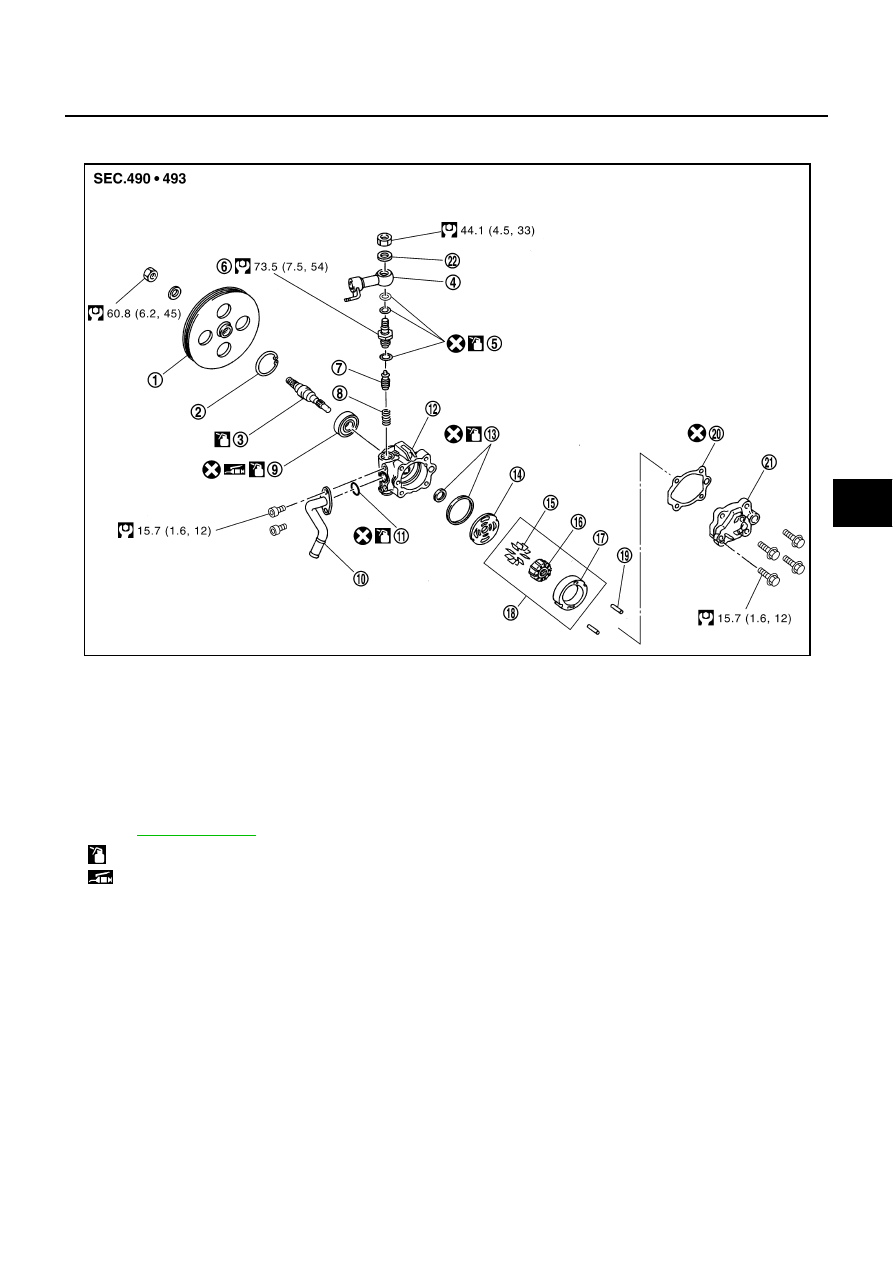
COMPONENTS
INSPECTION BEFORE DISASSEMBLY
Disassemble oil pump only when the following malfunctions occur.
●
If oil leakage is found on oil pump.
●
Oil pump pulley is damaged or deformed.
●
Performance of oil pump is low.
1.
Pulley
2.
Snap ring
3.
Drive shaft
4.
Joint
5.
O-ring
6.
Connector bolt
7.
Flow control valve
8.
Spring
9.
Oil seal
10.
Suction pipe
11.
O-ring
12.
Body assembly
13.
O-ring
14.
Side plate
15.
Vane
16.
Rotor
17.
Cam ring
18.
Cartridge
19.
Dowel pin
20.
Gasket
21.
Rear cover
22.
Copper washer
, and the followings for the symbols in the figure.
: Apply power steering fluid.
: Apply multi-purpose grease.
SGIA1187E
PS-32
POWER STEERING OIL PUMP
DISASSEMBLY
NOTE:
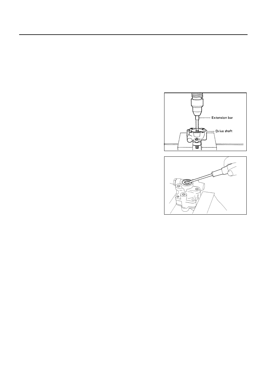
Secure oil pump in a vise if necessary.
CAUTION:
Use copper plates when securing in a vise.
1.
Remove rear cover mounting bolts, and then remove rear cover from body assembly.
2.
Remove gasket from body assembly.
3.
Remove dowel pin, cartridge and side plate from body assembly.
4.
Remove pulley mounting nut and washer, then remove pulley from drive shaft.
5.
Remove snap ring from drive shaft and press out it.
CAUTION:
When removing snap ring, be careful not to damage drive
shaft.
6.
Remove oil seal from body assembly using a flat-bladed screw-
driver.
7.
Remove O-ring from body assembly.
8.
Remove lock nut, and then remove copper washer, joint and O-
ring.
9.
Remove connector bolt, and then remove O-ring, flow control
valve and spring from body assembly
10. Remove mounting bolts of suction pipe, and then remove suc-
tion pipe from body assembly.
11. Remove O-ring from body assembly.
INSPECTION AFTER DISASSEMBLY
Body Assembly and Rear Cover Inspection
Check body assembly and rear cover for internal damage. Replace rear cover if it is damaged. Replace oil
pump assembly if body assembly is damaged.
Cartridge Assembly Inspection
Check cam ring, rotor and vane for damage. Replace cartridge assembly if there are.
Side Plate Inspection
Check side plate for damage. Replace side plate if there are.
Flow Control Valve Inspection
Check flow control valve and spring for damage. Replace if there are.
SST010B
SST034A
POWER STEERING OIL PUMP
PS-33
C
D
E
F
H
I
J
K
L
M
A
B
PS
ASSEMBLY
NOTE:
Secure oil pump in a vise if necessary.
CAUTION:
Use copper plates when securing in a vise.
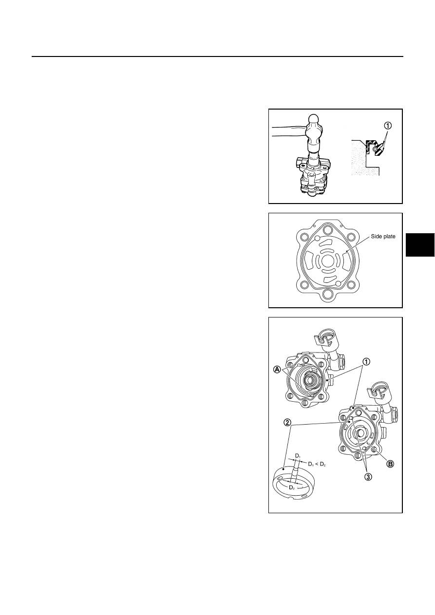
1.
Apply recommended grease to oil seal lips (1). Apply recom-
mended fluid to around oil seal, and then install oil seal to body
assembly.
2.
Apply recommended fluid to drive shaft, and press drive shaft
into body assembly, then install snap ring.
3.
Apply recommended fluid to O-ring, and then install O-ring into
body assembly.
4.
Install side plate to body assembly.
5.
Install dowel pin (3) into dowel pin hole (A), and then install cam
ring (2) pointing it's D
1
side toward the body assembly (1) side
as shown in the figure.
●
When installing cam ring, turn carved face with a letter E (B)
of it to rear cover.
CAUTION:
Do not confuse the assembling direction of cam ring. If
cam ring is installed facing the incorrect direction, it may
cause oil pump operation malfunction.
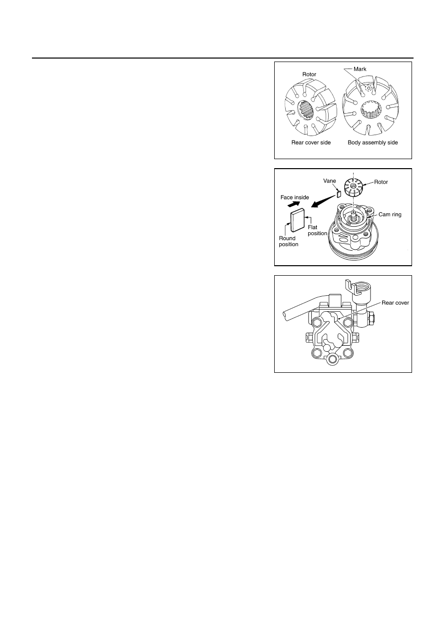
6.
Install rotor to body assembly.
SGIA1150E
SGIA0422E
SGIA1166E
PS-34
POWER STEERING OIL PUMP
●
When installing rotor, turn mark face on rotor to body assem-
bly.
7.
Install vane to rotor so that arc of vane faces cam ring side.
8.
Check if drive shaft turns smoothly.
9.
Install gasket to body assembly.
10. Install rear cover to body assembly, and then tighten mounting
bolts to the specified torque.
11. Install pulley and washer to drive shaft, and then tighten lock nut
at the specified torque.
12. Apply recommended fluid to O-ring. Install spring, flow control
valve and O-ring to body assembly, and then tighten connector
bolt to the specified torque.
13. Apply recommended fluid to O-ring . Install O-ring, joint and cop-
per washer to connector bolt, and then tighten lock nut to the
specified torque.
14. Apply recommended fluid to O-ring, and then install O-ring to
body assembly.
15. Install suction pipe to body assembly.
SGIA0989E
SGIA0613E
SGIA0425E
Нет комментариевНе стесняйтесь поделиться с нами вашим ценным мнением.
Текст