Infiniti M35/M45 Y50. Manual — part 6
LASER BEAM AIMING ADJUSTMENT
ACS-17
[ICC]
C
D
E
F
G
H
I
J
L
M
A
B
ACS
3.
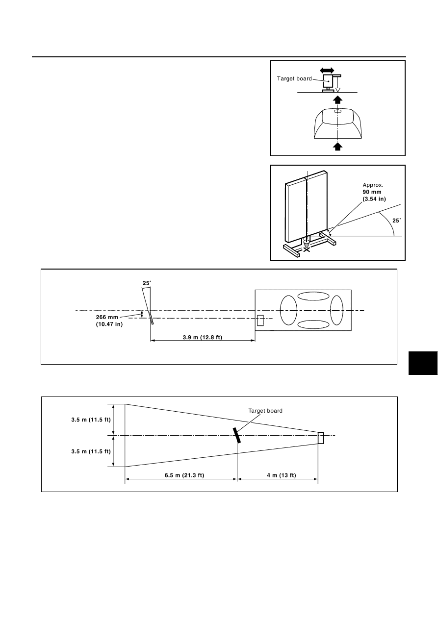
Adjust the position of the target board so that the extended line
that links the center of the rear window glass (the center of the
rear window defogger pattern) and the center of the windshield
(the setting part of the room mirror) align with the weight sus-
pended from the board.
4.
Remove the thread suspended to the right side of board and
suspend a thread with weight on tip on the center of the target
board. Then mark the point of weight on the ground.
5.
Pivot the edge of the target board 25
°
to either side.
NOTE:
Approx. 90 mm (3.54 in) shift rates the 25
°
movement.
NOTE:
The distance between center of laser beam axis and target board is 4 m (13 ft).
6.
Do not place anything in the space shown in the figure (view from top).
NOTE:
In case the space shown in the figure is not available, make a space by covering the side of the target
board with a 1400 mm (4.6 ft)-size frosted black board or black cloth.
PKIB8355E
PKIB8356E
PKIB8357E
PKIB8358E

ACS-18
[ICC]
LASER BEAM AIMING ADJUSTMENT
Aiming Adjustment
NKS004CQ
CAUTION:
●
Complete all necessary work for laser beam adjustment until the adjustment completes as shown
in the procedure. If the procedure does not complete, the ICC system is inoperable.
●
If CONSULT-II is used with no connection of CONSULT-II CONVERTER, malfunctions might be
detected in self-diagnosis depending on control unit which carry out CAN communication.
1.
Connect CONSULT-II and CONSULT-II CONVERTER, and then
touch “ICC” on “SELECT SYSTEM” screen.
If “ICC” is not indicated, go to
2.
Touch “WORK SUPPORT”.
3.
Touch “LASER BEAM ADJUST”.
4.
Touch “START”.
CAUTION:
If the adjustment screen does not appear on the CONSULT-
II screen in 10 seconds. After touching “LASER BEAM
ADJUST” screen, the following causes may be considered:
●
Target is not set accurately.
●
There is not enough space beside the target.
●
The range of laser beam aiming exceeds for improper
installation position.
–
Deformation of vehicle body.
–
Deformation of unit.
–
Deformation of bracket.
●
The area is not suitable for the adjustment work.
●
ICC sensor integrated unit is not clean.
BCIA0030E
BCIA0031E
SKIA6191E
PKIB8359E

LASER BEAM AIMING ADJUSTMENT
ACS-19
[ICC]
C
D
E
F
G
H
I
J
L
M
A
B
ACS
5.
After the CONSULT-II displays “ADJUST THE VERTICAL OF
LASER BEAM AIMING” turn the up-down direction adjusting
screw until “U/D CORRECT” value is set in the range of
±
4.
CAUTION:
Turn the screw slowly. The value change on display is
slower than actual movement of the ICC sensor integrated
unit. Wait for 2 seconds every time the screw is turned half
a rotation.
NOTE:
Turning the screw clockwise to laser beam is downward and
counterclockwise to laser beam is upward.
6.
When “U/D CORRECT” value indicates
±
4, confirm that the margin of value remains within
±
4 at least for
2 seconds with no equipment or hand touching the ICC sensor integrated unit.
When “COMPLETED THE VERTICAL AIMING OF LASER
BEAM” appears on screen, touch “END”.
CAUTION:
Be sure that the margin of “U/D CORRECT” is within
±
4 with
ICC sensor integrated unit is untouched.
7.
Confirm that “ADJUSTING AUTOMATIC HORIZONTAL LASER
BEAM AIMING” is on screen and wait for a while (maximum: 10
seconds).
PKIB8360E
PKIB8361E
PKIB8362E
PKIB8363E

ACS-20
[ICC]
LASER BEAM AIMING ADJUSTMENT
8.
Confirm that “NORMALLY COMPLETED” is displayed on CON-
SULT-II and close the aiming adjustment procedure by touching
“END”.
CAUTION:
Complete all the procedures once “LASER BEAM ADJUST”
mode is entered in CONSULT-II. When the procedure is dis-
continued, the ICC system is inoperable.
CHECK AFTER THE ADJUSTMENT
Test the ICC system operation by ICC system running test. Refer to
ACS-12, "ICC System Running Test"
.
PKIB8364E
Нет комментариевНе стесняйтесь поделиться с нами вашим ценным мнением.
Текст