Infiniti M35/M45 Y50. Manual — part 700
DTC P1564 ASCD STEERING SWITCH
EC-1273
[VK45DE]
C
D
E
F
G
H
I
J
K
L
M
A
EC
DTC Confirmation Procedure
NBS005MH
NOTE:
If DTC Confirmation Procedure has been previously conducted, always turn ignition switch OFF and wait at
least 10 seconds before conducting the next test.
WITH CONSULT-II
1.
Turn ignition switch ON.
2.
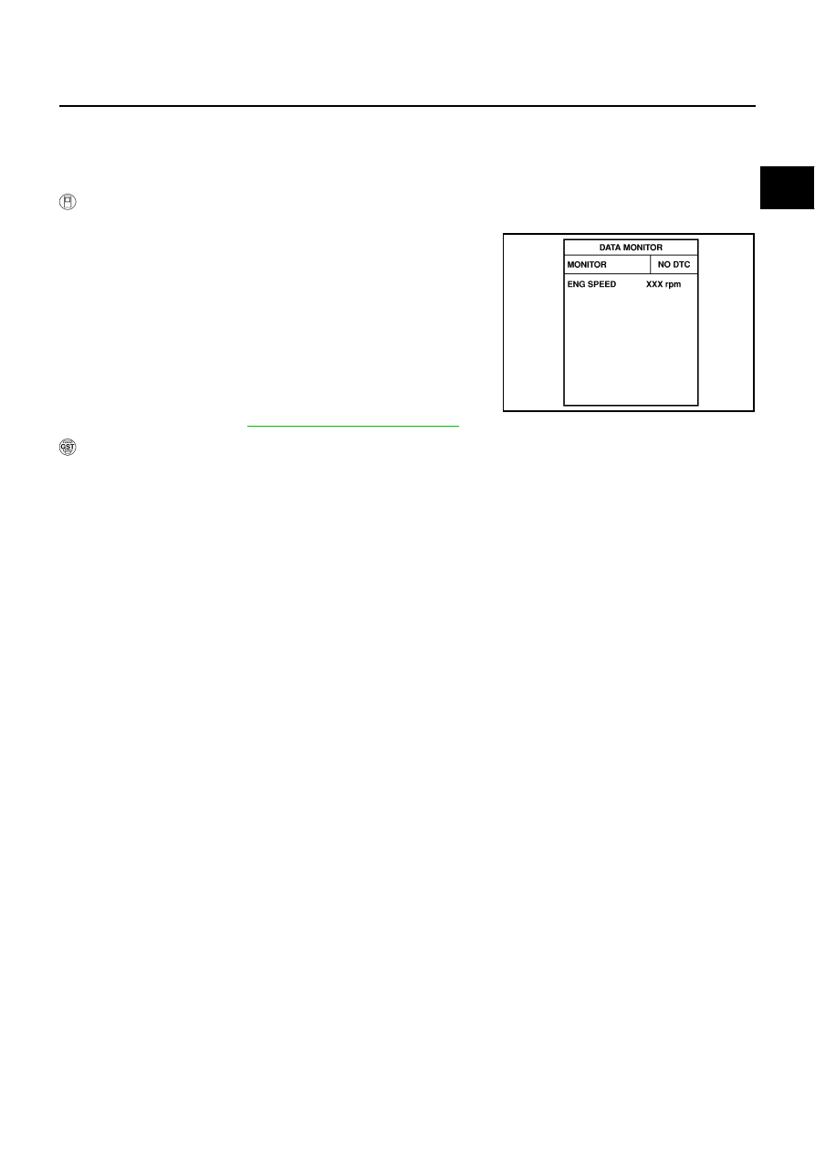
Select “DATA MONITOR” mode with CONSULT-II.
3.
Wait at least 10 seconds.
4.
Press MAIN switch for at least 10 seconds, then release it and
wait at least 10 seconds.
5.
Press CANCEL switch for at least 10 seconds, then release it
and wait at least 10 seconds.
6.
Press RESUME/ACCELERATE switch for at least 10 seconds,
then release it and wait at least 10 seconds.
7.
Press SET/COAST switch for at least 10 seconds, then release
it and wait at least 10 seconds.
8.
EC-1275, "Diagnostic Procedure"
WITH GST
Follow the procedure “WITH CONSULT-II” above.
SEF058Y
EC-1274
[VK45DE]
DTC P1564 ASCD STEERING SWITCH
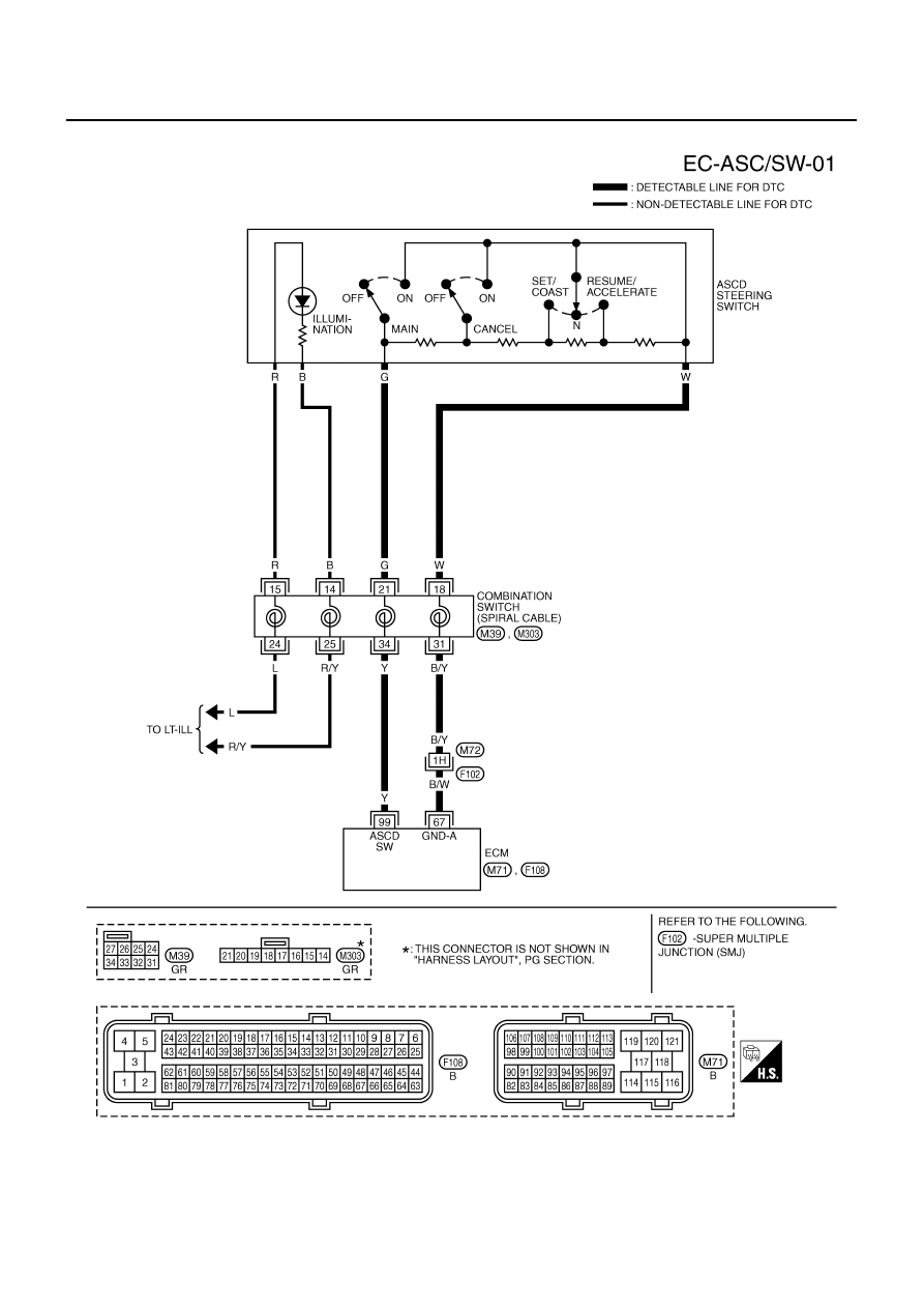
Wiring Diagram
NBS005MI
TBWT1048E
DTC P1564 ASCD STEERING SWITCH
EC-1275
[VK45DE]
C
D
E
F
G
H
I
J
K
L
M
A
EC
Specification data are reference values and are measured between each terminal and ground.
CAUTION:
Do not use ECM ground terminals when measuring input/output voltage. Doing so may result in dam-
age to the ECM's transistor. Use a ground other than ECM terminals, such as the ground.
Diagnostic Procedure
NBS005MJ
1.
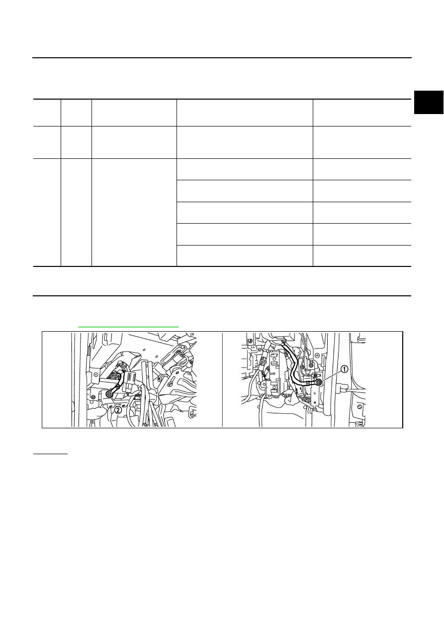
CHECK GROUND CONNECTIONS
1.
Turn ignition switch OFF.
2.
Loosen and retighten ground screws on the body.
Refer to
OK or NG
OK
>> GO TO 2.
NG
>> Repair or replace ground connections.
TER-
MINAL
NO.
WIRE
COLOR
ITEM
CONDITION
DATA (DC Voltage)
67
B/W
Sensor ground
(ASCD steering switch
[Engine is running]
●
Warm-up condition
●
Idle speed
Approximately 0V
99
Y
ASCD steering switch
[Ignition switch: ON]
●
ASCD steering switch: OFF
Approximately 4V
[Ignition switch: ON]
●
MAIN switch: Pressed
Approximately 0V
[Ignition switch: ON]
●
CANCEL switch: Pressed
Approximately 1V
[Ignition switch: ON]
●
RESUME/ACCELERATE switch: Pressed
Approximately 3V
[Ignition switch: ON]
●
SET/COAST switch: Pressed
Approximately 2V
1.
Body ground M70
2.
Body ground M16
PBIB2782E
EC-1276
[VK45DE]
DTC P1564 ASCD STEERING SWITCH
2.
CHECK ASCD STEERING SWITCH CIRCUIT
With CONSULT-II
1.
Turn ignition switch ON.
2.
Select “MAIN SW”, “CANCEL SW”, “RESUME/ACC SW” and “SET SW” in “DATA MONITOR” mode with
CONSULT-II.
3.
Check each item indication under the following conditions.
Without CONSULT-II
1.
Turn ignition switch ON.
2.
Check voltage between ECM terminal 99 and ground with press-
ing each button.
OK or NG
OK
>> GO TO 8.
NG
>> GO TO 3.
3.
CHECK ASCD STEERING SWITCH GROUND CIRCUIT FOR OPEN AND SHORT
1.
Turn ignition switch OFF.
2.
Disconnect ECM harness connector.
3.
Disconnect combination switch harness connector M303.
4.
Check harness continuity between combination switch terminal 18 and ECM terminal 67.
Refer to Wiring Diagram.
5.
Also check harness for short to ground and short to power.
OK or NG
OK
>> GO TO 5.
NG
>> GO TO 4.
Switch Monitor
item
Condition
Indication
MAIN switch
MAIN SW
Pressed
ON
Released
OFF
CANCEL switch
CANCEL SW
Pressed
ON
Released
OFF
RESUME/ACCELERATE
switch
RESUME/ACC SW
Pressed
ON
Released
OFF
SET/COAST switch
SET SW
Pressed
ON
Released
OFF
SEC006D
Switch
Condition
Voltage [V]
MAIN switch
Pressed
Approx. 0
Released
Approx. 4
CANCEL switch
Pressed
Approx. 1
Released
Approx. 4
RESUME/ACCELERATE
switch
Pressed
Approx. 3
Released
Approx. 4
SET/COAST switch
Pressed
Approx. 2
Released
Approx. 4
PBIB0311E
Continuity should exist.
Нет комментариевНе стесняйтесь поделиться с нами вашим ценным мнением.
Текст