Infiniti M35/M45 Y50. Manual — part 738
REFRIGERANT PRESSURE SENSOR
EC-1425
[VK45DE]
C
D
E
F
G
H
I
J
K
L
M
A
EC
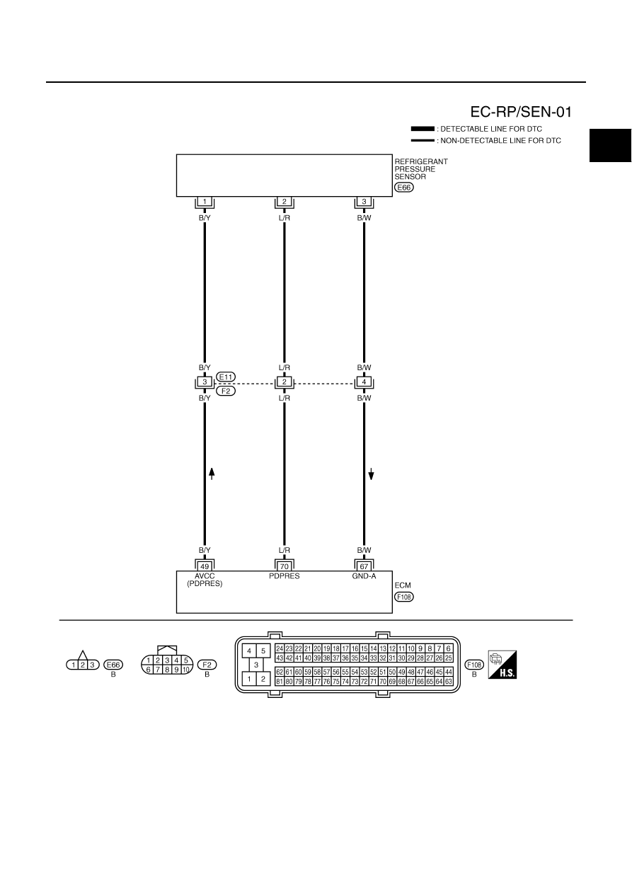
Wiring Diagram
NBS005Q8
TBWT1067E
EC-1426
[VK45DE]
REFRIGERANT PRESSURE SENSOR
Specification data are reference values and are measured between each terminal and ground.
CAUTION:
Do not use ECM ground terminals when measuring input/output voltage. Doing so may result in dam-
age to the ECM's transistor. Use a ground other than ECM terminals, such as the ground.
Diagnostic Procedure
NBS005Q9
1.
CHECK REFRIGERANT PRESSURE SENSOR OVERALL FUNCTION
1.
Start engine and warm it up to normal operating temperature.
2.
Turn A/C switch and blower fan switch ON.
3.
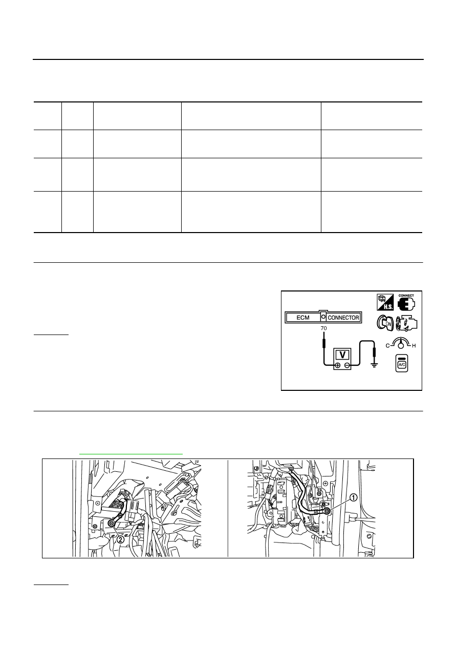
Check voltage between ECM terminal 70 and ground with CON-
SULT-II or tester.
OK or NG
OK
>> INSPECTION END
NG
>> GO TO 2.
2.
CHECK GROUND CONNECTIONS
1.
Turn A/C switch and blower fan switch OFF.
2.
Turn ignition switch OFF.
3.
Loosen and retighten ground screws on the body.
Refer to
OK or NG
OK
>> GO TO 3.
NG
>> Repair or replace ground connections.
TER-
MINAL
NO.
WIRE
COLOR
ITEM
CONDITION
DATA (DC Voltage)
49
B/Y
Sensor power supply
(Refrigerant pressure sen-
sor)
[Ignition switch: ON]
Approximately 5V
67
B/W
Sensor ground
(Refrigerant pressure sen-
sor)
[Engine is running]
●
Warm-up condition
●
Idle speed
Approximately 0V
70
L/R
Refrigerant pressure sensor
[Engine is running]
●
Warm-up condition
●
Both A/C switch and blower fan motor
switch: ON (Compressor operates)
1.0 - 4.0V
Voltage: 1.0 - 4.0V
PBIB1188E
1.
Body ground M70
2.
Body ground M16
PBIB2782E
REFRIGERANT PRESSURE SENSOR
EC-1427
[VK45DE]
C
D
E
F
G
H
I
J
K
L
M
A
EC
3.
CHECK REFRIGERANT PRESSURE SENSOR POWER SUPPLY CIRCUIT
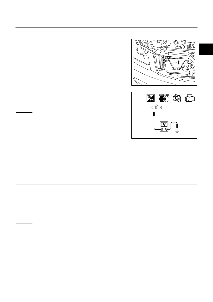
1.
Disconnect refrigerant pressure sensor (1) harness connector.
2.
Turn ignition switch ON.
3.
Check voltage between refrigerant pressure sensor terminal 1
and ground with CONSULT-II or tester.
OK or NG
OK
>> GO TO 5.
NG
>> GO TO 4.
4.
DETECT MALFUNCTIONING PART
Check the following.
●
Harness connectors E11, F2
●
Harness for open or short between ECM and refrigerant pressure sensor
>> Repair open circuit or short to ground or short to power in harness or connectors.
5.
CHECK REFRIGERANT PRESSURE SENSOR GROUND CIRCUIT FOR OPEN AND SHORT
1.
Turn ignition switch OFF.
2.
Disconnect ECM harness connector.
3.
Check harness continuity between refrigerant pressure sensor terminal 3 and ECM terminal 67.
Refer to Wiring Diagram.
4.
Also check harness for short to ground and short to power.
OK or NG
OK
>> GO TO 7.
NG
>> GO TO 6.
6.
DETECT MALFUNCTIONING PART
Check the following.
●
Harness connectors E11, F2
●
Harness for open or short between ECM and refrigerant pressure sensor
>> Repair open circuit or short to ground or short to power in harness or connectors.
PBIA9537J
Voltage: Approximately 5V
PBIB0188E
Continuity should exist.
EC-1428
[VK45DE]
REFRIGERANT PRESSURE SENSOR
7.
CHECK REFRIGERANT PRESSURE SENSOR INPUT SIGNAL CIRCUIT FOR OPEN AND SHORT
1.
Check harness continuity between ECM terminal 70 and refrigerant pressure sensor terminal 2.
Refer to Wiring Diagram.
2.
Also check harness for short to ground and short to power.
OK or NG
OK
>> GO TO 9.
NG
>> GO TO 8.
8.
DETECT MALFUNCTIONING PART
Check the following.
●
Harness connectors E11, F2
●
Harness for open or short between ECM and refrigerant pressure sensor
>> Repair open circuit or short to ground or short to power in harness or connectors.
9.
CHECK INTERMITTENT INCIDENT
Refer to
EC-857, "TROUBLE DIAGNOSIS FOR INTERMITTENT INCIDENT"
.
OK or NG
OK
>> Replace refrigerant pressure sensor.
NG
>> Repair or replace.
Removal and Installation
NBS005QA
REFRIGERANT PRESSURE SENSOR
Refer to
ATC-166, "Removal and Installation of Refrigerant Pressure Sensor"
Continuity should exist.
Нет комментариевНе стесняйтесь поделиться с нами вашим ценным мнением.
Текст