Infiniti M35/M45 Y50. Manual — part 42
TROUBLE DIAGNOSIS
AT-91
D
E
F
G
H
I
J
K
L
M
A
B
AT
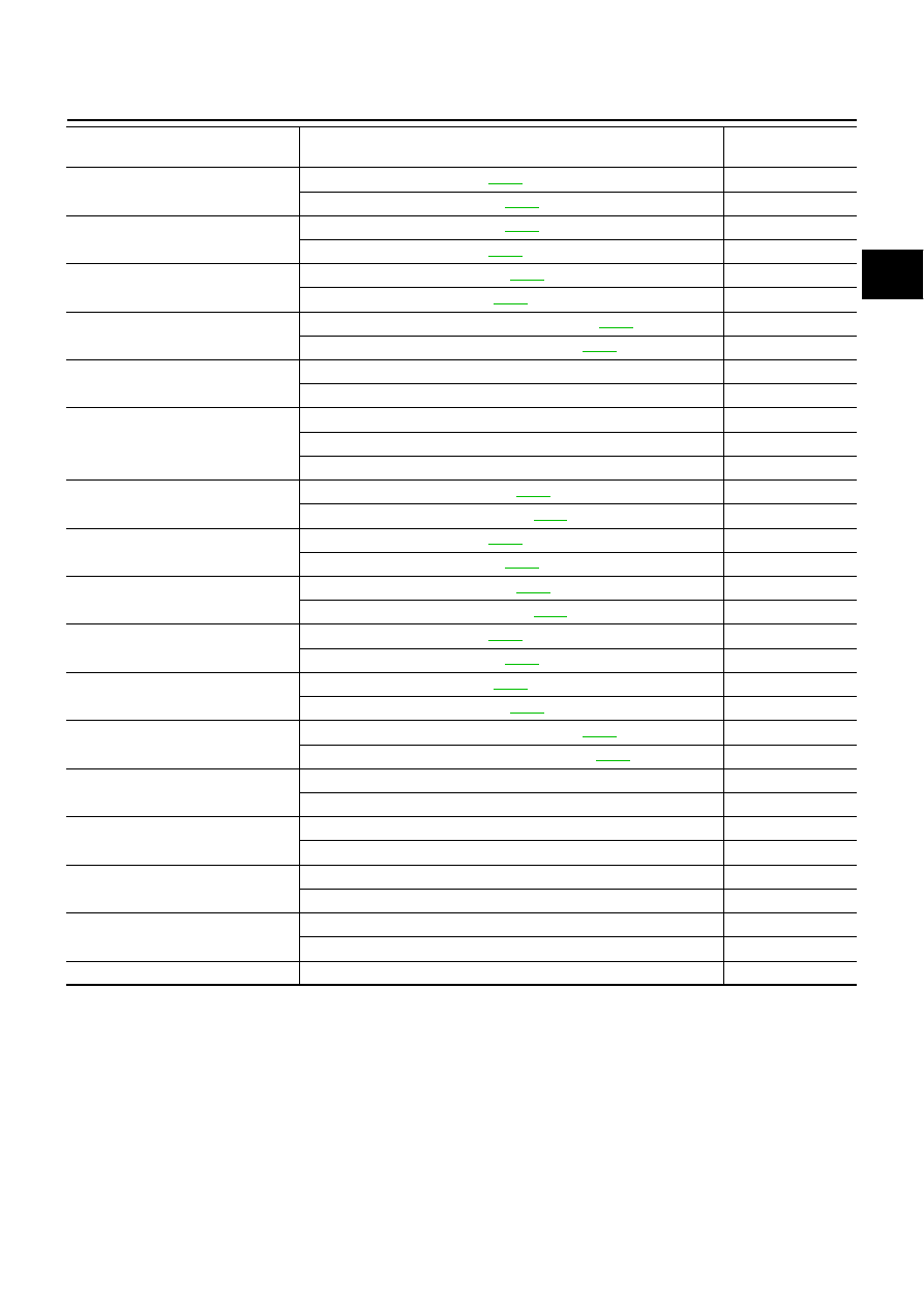
FR/B SOLENOID
Front brake engaged. Refer to
.
0.6 - 0.8 A
Front brake disengaged. Refer to
0 - 0.05 A
I/C SOLENOID
Input clutch disengaged. Refer to
.
0.6 - 0.8 A
Input clutch engaged. Refer to
.
0 - 0.05 A
D/C SOLENOID
Direct clutch disengaged. Refer to
0.6 - 0.8 A
Direct clutch engaged. Refer to
0 - 0.05 A
HLR/C SOL
High and low reverse clutch disengaged. Refer to
.
0.6 - 0.8 A
High and low reverse clutch engaged. Refer to
0 - 0.05 A
STARTER RELAY
Selector lever in “N”, “P” positions.
ON
Selector lever in “R”, “D” positions.
OFF
SLCT LVR POSI
Selector lever in “N”, “P” positions.
N/P
Selector lever in “R” position.
R
Selector lever in “D” position.
D
ON OFF SOL
Low coast brake engaged. Refer to
.
ON
Low coast brake disengaged. Refer to
.
OFF
ATF PRES SW 1
Front brake engaged. Refer to
.
ON
Front brake disengaged. Refer to
.
OFF
ATF PRES SW 2
Low coast brake engaged. Refer to
.
ON
Low coast brake disengaged. Refer to
.
OFF
ATF PRES SW 3
Input clutch engaged. Refer to
.
ON
Input clutch disengaged. Refer to
.
OFF
ATF PRES SW 5
Direct clutch engaged. Refer to
.
ON
Direct clutch disengaged. Refer to
.
OFF
ATF PRES SW 6
High and low reverse clutch engaged. Refer to
.
ON
High and low reverse clutch disengaged Refer to
.
OFF
MANU MODE SW
Manual shift gate position (neutral)
ON
Other than the above
OFF
NON M-MODE SW
Manual shift gate position
OFF
Other than the above
ON
UP SW LEVER
Selector lever: + side
ON
Other than the above
OFF
DOWN SW LEVER
Selector lever: - side
ON
Other than the above
OFF
GEAR
During driving
1, 2, 3, 4, 5
Item name
Condition
Display value
(Approx.)
AT-92
TROUBLE DIAGNOSIS
CONSULT-II SETTING PROCEDURE
Refer to
GI-38, "CONSULT-II Start Procedure"
SELF-DIAGNOSTIC RESULT MODE
After performing self-diagnosis, place check marks for results on the
Reference pages are provided following the items.
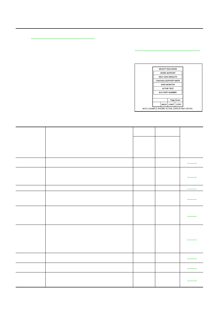
Operation Procedure
1.
Touch “SELF-DIAG RESULTS” on “SELECT DIAG MODE”
screen.
Display shows malfunction experienced since the last erasing
operation.
Display Items List
X: Applicable, —: Not applicable
BCIA0031E
Items (CONSULT-
II screen terms)
Malfunction is detected when...
TCM self-
diagnosis
OBD-II (DTC)
Reference
page
“A/T” with
CONSULT-II
MIL indicator
lamp*1,
“ENGINE” with
CONSULT-II or
GST
CAN COMM CIR-
CUIT
●
When TCM is not transmitting or receiving CAN communi-
cation signal for 2 seconds or more.
U1000
U1000
STARTER RELAY/
CIRC
●
If this signal is ON other than in “P” or “N” position, this is
judged to be a malfunction.
(And if it is OFF in “P” or “N” position, this too is judged to
be a malfunction.)
P0615
—
TCM
●
TCM is malfunctioning
P0700
P0700
PNP SW/CIRC
●
PNP switch 1-4 signals input with impossible pattern.
●
“P” position is detected from “N” position without any other
position being detected in between.
P0705
P0705
TURBINE REV S/
CIRC
●
TCM does not receive the proper voltage signal from the
sensor.
●
TCM detects an irregularity only at position of 4th gear for
turbine revolution sensor 2.
P0717
P0717
VEH SPD SEN/
CIR AT
●
Signal from vehicle speed sensor A/T (revolution sensor)
not input due to cut line or the like.
●
Unexpected signal input during running.
●
After ignition switch is turned ON, unexpected signal input
from vehicle speed sensor MTR before the vehicle starts
moving.
P0720
P0720
ENGINE SPEED
SIG
●
TCM does not receive the CAN communication signal from
the ECM.
P0725
P0725*3
TCC SOLENOID/
CIRC
●
Normal voltage not applied to solenoid due to cut line,
short, or the like.
P0740
P0740
A/T TCC S/V
FNCTN
●
A/T cannot perform lock-up even if electrical circuit is good.
●
TCM detects as irregular by comparing difference value
with slip rotation.
P0744
P0744*2

TROUBLE DIAGNOSIS
AT-93
D
E
F
G
H
I
J
K
L
M
A
B
AT
L/PRESS SOL/
CIRC
●
Normal voltage not applied to solenoid due to cut line,
short, or the like.
●
TCM detects as irregular by comparing target value with
monitor value.
P0745
P0745
TP SEN/CIRC A/T
●
TCM does not receive the proper accelerator pedal position
signals (input by CAN communication) from ECM.
P1705
P1705*3
ATF TEMP SEN/
CIRC
●
During running, the A/T fluid temperature sensor signal
voltage is excessively high or low.
P1710
P0710
VEH SPD SE/
CIR·MTR
●
Signal (CAN communication) from vehicle speed sensor
MTR not input due to cut line or the like.
●
Unexpected signal input during running.
P1721
—
A/T INTERLOCK
●
Except during shift change, the gear position and ATF pres-
sure switch states are monitored and comparative judge-
ment made.
P1730
P1730
A/T 1ST E/BRAK-
ING
●
Each ATF pressure switch and solenoid current is moni-
tored and if a pattern is detected having engine braking 1st
gear other than in the M1 position, a malfunction is
detected.
P1731
—
I/C SOLENOID/
CIRC
●
Normal voltage not applied to solenoid due to functional
malfunction, cut line, short, or the like.
●
TCM detects as irregular by comparing target value with
monitor value.
P1752
P1752
I/C SOLENOID
FNCTN
●
TCM detects that actual gear ratio is irregular, and relation
between gear position and condition of ATF pressure
switch 3 is irregular during depressing accelerator pedal.
(Other than during shift change.)
●
TCM detects that relation between gear position and condi-
tion of ATF pressure switch 3 is irregular during releasing
accelerator pedal. (Other than during shift change.)
P1754
P1754*2
FR/B SOLENOID/
CIRC
●
Normal voltage not applied to solenoid due to functional
malfunction, cut line, short, or the like.
●
TCM detects as irregular by comparing target value with
monitor value.
P1757
P1757
FR/B SOLENOID
FNCT
●
TCM detects that actual gear ratio is irregular, and relation
between gear position and condition of ATF pressure
switch 1 is irregular during depressing accelerator pedal.
(Other than during shift change.)
●
TCM detects that relation between gear position and condi-
tion of ATF pressure switch 1 is irregular during releasing
accelerator pedal. (Other than during shift change.)
P1759
P1759*2
D/C SOLENOID/
CIRC
●
Normal voltage not applied to solenoid due to cut line,
short, or the like.
●
TCM detects as irregular by comparing target value with
monitor value.
P1762
P1762
Items (CONSULT-
II screen terms)
Malfunction is detected when...
TCM self-
diagnosis
OBD-II (DTC)
Reference
page
“A/T” with
CONSULT-II
MIL indicator
lamp*1,
“ENGINE” with
CONSULT-II or
GST

AT-94
TROUBLE DIAGNOSIS
*1: Refer to
EC-70, "Malfunction Indicator Lamp (MIL)"
(for VQ35DE engine),
EC-772, "Malfunction Indicator Lamp (MIL)"
(for VK45DE
engine).
*2: These malfunctions cannot be displayed MIL if another malfunction is assigned to MIL.
D/C SOLENOID
FNCTN
●
TCM detects that actual gear ratio is irregular, and relation
between gear position and condition of ATF pressure
switch 5 is irregular during depressing accelerator pedal.
(Other than during shift change.)
●
TCM detects that relation between gear position and condi-
tion of ATF pressure switch 5 is irregular during releasing
accelerator pedal. (Other than during shift change.)
P1764
P1764*2
HLR/C SOL/CIRC
●
Normal voltage not applied to solenoid due to functional
malfunction, cut line, short, or the like.
●
TCM detects as irregular by comparing target value with
monitor value.
P1767
P1767
HLR/C SOL
FNCTN
●
TCM detects that actual gear ratio is irregular, and relation
between gear position and condition of ATF pressure
switch 6 is irregular during depressing accelerator pedal.
(Other than during shift change.)
●
TCM detects that relation between gear position and condi-
tion of ATF pressure switch 6 is irregular during releasing
accelerator pedal. (Other than during shift change.)
P1769
P1769*2
LC/B SOLENOID/
CIRC
●
Normal voltage not applied to solenoid due to functional
malfunction, cut line, short, or the like.
P1772
P1772
LC/B SOLENOID
FNCT
●
TCM detects an improper voltage drop when it tries to oper-
ate the solenoid valve.
●
Condition of ATF pressure switch 2 is different from monitor
value, and relation between gear position and actual gear
ratio is irregular.
P1774
P1774*2
MANU MODE SW/
CIRC
●
When an impossible pattern of switch signals is detected, a
malfunction is detected.
P1815
—
ATF PRES SW 1/
CIRC
●
TCM detects that actual gear ratio is normal, and relation
between gear position and condition of ATF pressure
switch 1 is irregular during depressing accelerator pedal.
(Other than during shift change.)
P1841
—
ATF PRES SW 3/
CIRC
●
TCM detects that actual gear ratio is normal, and relation
between gear position and condition of ATF pressure
switch 3 is irregular during depressing accelerator pedal.
(Other than during shift change.)
P1843
—
ATF PRES SW 5/
CIRC
●
TCM detects that actual gear ratio is normal, and relation
between gear position and condition of ATF pressure
switch 5 is irregular during depressing accelerator pedal.
(Other than during shift change.)
P1845
—
ATF PRES SW 6/
CIRC
●
TCM detects that actual gear ratio is normal, and relation
between gear position and condition of ATF pressure
switch 6 is irregular during depressing accelerator pedal.
(Other than during shift change.)
P1846
—
NO DTC IS
DETECTED FUR-
THER TESTING
MAY BE
REQUIRED
●
No NG item has been detected.
X
X
—
Items (CONSULT-
II screen terms)
Malfunction is detected when...
TCM self-
diagnosis
OBD-II (DTC)
Reference
page
“A/T” with
CONSULT-II
MIL indicator
lamp*1,
“ENGINE” with
CONSULT-II or
GST
Нет комментариевНе стесняйтесь поделиться с нами вашим ценным мнением.
Текст