Infiniti M35/M45 Y50. Manual — part 405
TROUBLE DIAGNOSIS
EC-93
[VQ35DE]
C
D
E
F
G
H
I
J
K
L
M
A
EC
5.
PERFORM DTC CONFIRMATION PROCEDURE
Perform DTC Confirmation Procedure for the displayed DTC*
1
, and then make sure that DTC*
1
is detected
again.
At this time, always connect CONSULT-II to the vehicle, and check diagnostic results in real time on “DATA
MONITOR (AUTO TRIG)”.
If two or more DTCs*
1
are detected, refer to
EC-96, "DTC Inspection Priority Chart"
diagnosis order.
NOTE:
●
Freeze frame data*
2
is useful if the DTC*
1
is not detected.
●
Perform Overall Function Check if DTC Confirmation Procedure is not included on Service Manual. This
simplified check procedure is an effective alternative though DTC*
1
cannot be detected during this check.
If the result of Overall Function Check is NG, it is the same as the detection of DTC*
1
by DTC Confirma-
tion Procedure.
Is DTC*
1
detected?
Yes
>> GO TO 10.
No
EC-153, "TROUBLE DIAGNOSIS FOR INTERMITTENT INCIDENT"
.
6.
PERFORM BASIC INSPECTION
Perform
.
With CONSULT-II>>GO TO 7.
Without CONSULT-II>>GO TO 9.
7.
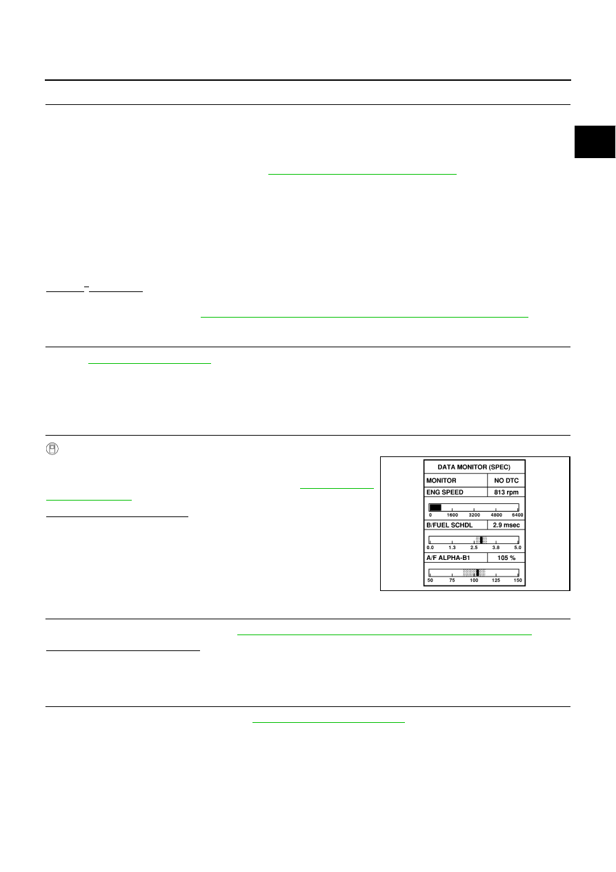
PERFORM DATA MONITOR (SPEC) MODE
With CONSULT-II
Make sure that “MAS A/F SE-B1”, “B/FUEL SCHDL”, and “A/F
ALPHA-B1”, “A/F ALPHA-B2” are within the SP value using CON-
SULT-II “DATA MONITOR (SPEC)” mode. Refer to
Are they within the SP value?
Yes
>> GO TO 9.
No
>> GO TO 8.
8.
DETECT MALFUNCTIONING PART BY TROUBLE DIAGNOSIS - SPECIFICATION VALUE
Detect malfunctioning part according to
EC-143, "TROUBLE DIAGNOSIS - SPECIFICATION VALUE"
Is malfunctioning part detected?
Yes
>> GO TO 11.
No
>> GO TO 9.
9.
DETECT MALFUNCTIONING SYSTEM BY SYMPTOM MATRIX CHART
Detect malfunctioning system according to
based on the confirmed symptom
in step 4, and determine the trouble diagnosis order based on possible causes and symptom.
>> GO TO 10.
SEF601Z

EC-94
[VQ35DE]
TROUBLE DIAGNOSIS
10.
DETECT MALFUNCTIONING PART BY DIAGNOSTIC PROCEDURE
Inspect according to Diagnostic Procedure of the system.
NOTE:
The Diagnostic Procedure in EC section described based on open circuit inspection. A short circuit inspection
is also required for the circuit check in the Diagnostic Procedure. For details, refer to Circuit Inspection in
28, "How to Perform Efficient Diagnosis for an Electrical Incident"
Is malfunctioning part detected?
Yes
>> GO TO 11.
No
>> Monitor input data from related sensors or check voltage of related ECM terminals using CON-
SULT-II. Refer to
EC-138, "CONSULT-II Reference Value in Data Monitor"
11.
REPAIR OR REPLACE THE MALFUNCTIONING PART
1.
Repair or replace the malfunctioning part.
2.
Reconnect parts or connectors disconnected during Diagnostic Procedure again after repair and replace-
ment.
3.
Check DTC. If DTC is displayed, erase it, refer to
EC-68, "HOW TO ERASE EMISSION-RELATED DIAG-
.
>> GO TO 12.
12.
FINAL CHECK
When DTC was detected in step 2, perform DTC Confirmation Procedure or Overall Function Check again,
and then make sure that the malfunction have been repaired securely.
When symptom was described from the customer, refer to confirmed symptom in step 3 or 4, and make sure
that the symptom is not detected.
OK or NG
NG (DTC*
1
is detected)>>GO TO 10.
NG (Symptom remains)>>GO TO 6.
OK
>> 1. Before returning the vehicle to the customer, make sure to erase unnecessary DTC*
1
in ECM
and TCM (Transmission Control Module). (Refer to
EC-68, "HOW TO ERASE EMISSION-
RELATED DIAGNOSTIC INFORMATION"
and
2. If the completion of SRT is needed, drive vehicle under the specific driving pattern. Refer to
3. INSPECTION END
*1: Include 1st trip DTC.
*2: Include 1st trip freeze frame data.
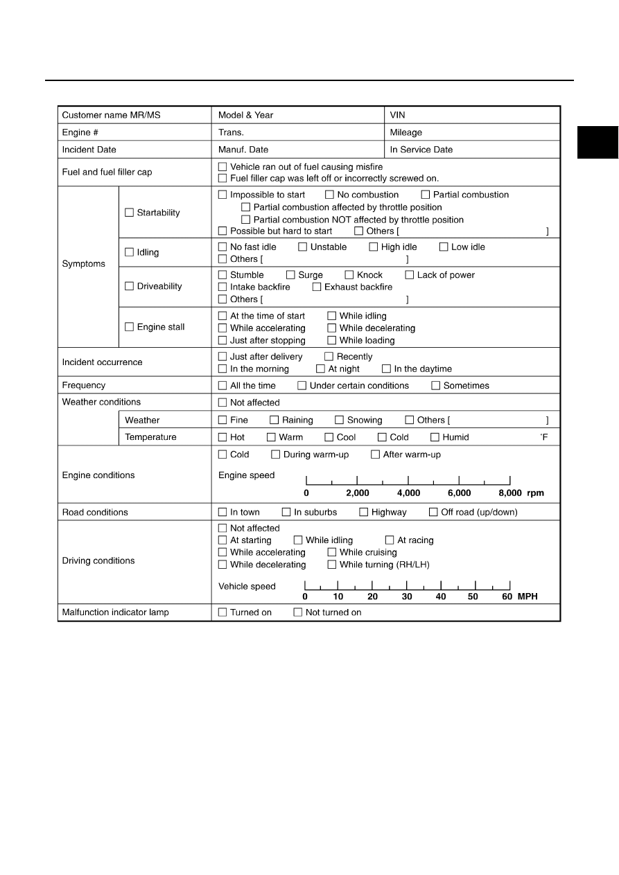
DIAGNOSTIC WORKSHEET
Description
There are many operating conditions that lead to the malfunction of
engine components. A good grasp of such conditions can make trou-
bleshooting faster and more accurate.
In general, each customer feels differently about a incident. It is
important to fully understand the symptoms or conditions for a cus-
tomer complaint.
Utilize a diagnostic worksheet like the one on the next page in order
to organize all the information for troubleshooting.
Some conditions may cause the MIL to come on steady or blink and
DTC to be detected. Examples:
●
Vehicle ran out of fuel, which caused the engine to misfire.
●
Fuel filler cap was left off or incorrectly screwed on, allowing fuel
to evaporate into the atmosphere.
SEF907L
TROUBLE DIAGNOSIS
EC-95
[VQ35DE]
C
D
E
F
G
H
I
J
K
L
M
A
EC
Worksheet Sample
MTBL0017

EC-96
[VQ35DE]
TROUBLE DIAGNOSIS
DTC Inspection Priority Chart
NBS004SZ
If some DTCs are displayed at the same time, perform inspections one by one based on the following priority
chart.
NOTE:
●
If DTC U1000 or U1001 is displayed with other DTC, first perform the trouble diagnosis for DTC
U1000, U1001. Refer to
EC-161, "DTC U1000, U1001 CAN COMMUNICATION LINE"
.
●
If DTC U1010 is displayed with other DTC, first perform the trouble diagnosis for DTC U1010. Refer
to
EC-164, "DTC U1010 CAN COMMUNICATION"
Priority
Detected items (DTC)
1
●
U1000 U1001 CAN communication line
●
U1010 CAN communication
●
P0101 P0102 P0103 Mass air flow sensor
●
P0112 P0113 P0127 Intake air temperature sensor
●
P0117 P0118 P0125 Engine coolant temperature sensor
●
P0122 P0123 P0222 P0223 P1225 P1226 P2135 Throttle position sensor
●
P0128 Thermostat function
●
P0181 P0182 P0183 Fuel tank temperature sensor
●
P0327 P0328 Knock sensor
●
P0335 Crankshaft position sensor (POS)
●
P0340 P0345 Camshaft position sensor (PHASE)
●
P0460 P0461 P0462 P0463 Fuel level sensor
●
P0500 Vehicle speed sensor
●
P0643 Sensor power supply
●
P0605 ECM
●
P0700 TCM
●
P0705 P0850 Park/Neutral position (PNP) switch
●
P1550 P1551 P1552 P1553 P1554 Battery current sensor
●
P1610 - P1615 NATS
●
P2122 P2123 P2127 P2128 P2138 Accelerator pedal position sensor
Нет комментариевНе стесняйтесь поделиться с нами вашим ценным мнением.
Текст