Infiniti M35/M45 Y50. Manual — part 821
REAR WINDOW DEFOGGER
GW-81
C
D
E
F
G
H
J
K
L
M
A
B
GW
CONSULT-II Function (BCM)
NIS0028Q
CONSULT-II can display each diagnostic item using the diagnostic test modes shown following.
CONSULT-II START PROCEDURE
Refer to
GI-38, "CONSULT-II Start Procedure"
DATA MONITOR
Display Item List
ACTIVE TEST
Display Item List
CONSULT-II Function (IPDM E/R)
NIS0028R
CONSULT-II can display each diagnostic item using the diagnostic test mode shown following.
CONSULT-II START PROCEDURE
Refer to
GI-38, "CONSULT-II Start Procedure"
DATA MONITOR
ACTIVE TEST
BCM diagnostic test item
Check item diagnostic
test mode
Content
REAR DEFOGGER
Data monitor
Displays the input data of BCM in real time.
Active test
Gives a drive signal to a load to check the operation.
Monitor item “Operation”
Content
REAR DEF SW
“ON/OFF”
Displays “Press (ON)/others (OFF)” status determined with the rear window defogger
switch.
IGN ON SW
“ON/OFF”
Displays “IGN (ON)/OFF” status determined with the ignition switch signal.
Test item
Content
REAR DEFOGGER
Gives a drive signal to the rear window defogger to activate it.
IPDM E/R diagnostic test
item
Check item diagnostic
test mode
Content
REAR DEFOGGER
Data monitor
Displays the input data of BCM in real time.
Active test
Gives a drive signal to a load to check the operation.
Monitored Item
Description
RR DEF REQ
Indicates [ON/OFF] condition of rear window defogger function by IPDM E/R.
Test Item
Description
REAR DEFOGGER
This test is able to check rear window defogger operation. Rear window defogger operates when
“ON” on CONSULT-II screen is touched.
GW-82
REAR WINDOW DEFOGGER
Work Flow
NIS0022P
1.
Check the symptom and customer's requests.
2.
Understand the outline of system. Refer to
3.
According to the trouble diagnosis chart, repair or replace the cause of the malfunction. Refer to
"Trouble Diagnoses Symptom Chart"
.
4.
Does rear window defogger operate normally? YES: GO TO 5, NO: GO TO 3.
5.
INSPECTION END.
Trouble Diagnoses Symptom Chart
NIS0022Q
Make sure other systems using the signal of the following systems operate normally.
*1: With navigation system
*2: Without navigation system
Symptom
Diagnoses / Service procedure
Refer to page
Rear window defogger and door mirror defogger do not
operate.
1. Check BCM power supply and ground circuit
2. Check IPDM E/R auto active test
3. Check rear window defogger switch circuit
4. Check rear window defogger power supply circuit
5. Replace IPDM E/ R
Rear window defogger does not operate but both of door
mirror defogger operate.
1.Check rear window defogger circuit
2.Check filament
Both of door mirror defogger does not operated but rear
window defogger operates.
Check door mirror defogger power supply circuit
Driver side door mirror defogger does not operate.
Check driver side door mirror defogger circuit
Passenger side door mirror defogger does not operate.
Check passenger side door mirror defogger circuit
Rear window defogger switch does not light, and rear win-
dow defogger is not displayed on the display.
But rear window defogger operates.
Check rear window defogger signal
1
2
Rear window defogger switch does not light, but rear win-
dow defogger operates
Replace multi-function switch
REAR WINDOW DEFOGGER
GW-83
C
D
E
F
G
H
J
K
L
M
A
B
GW
Check BCM Power Supply and Ground Circuit
NIS0022R
First perform the “SELF-DIAG RESULTS” in “BCM” with CONSULT-II, when perform the each trouble
diagnosis. Refer to
BCS-13, "CAN Communication Inspection Using CONSULT-II (Self-Diagnosis)"
1.
CHECK FUSE
●
Check 15A fuse [No.1, located in the fuse block (J/B)]
●
Check 10A fuse [No.21, located in the fuse block (J/B)]
●
Check 50A fusible link (letter F located in the fuse and fusible link box).
NOTE:
Refer to
GW-71, "Component Parts and Harness Connector Location"
.
OK or NG
OK
>> GO TO 2.
NG
>> If fuse is blown out, be sure to eliminate cause of malfunction before installing new fuse. Refer to
PG-3, "POWER SUPPLY ROUTING CIRCUIT"
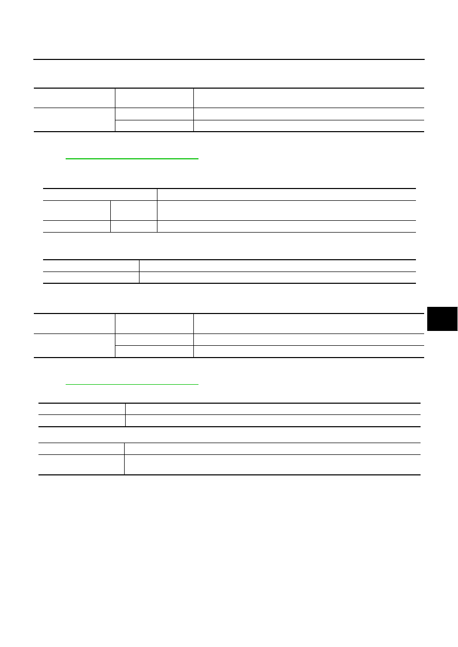
2.
CHECK POWER SUPPLY CIRCUIT
Check voltage between BCM connector and ground.
OK or NG
OK
>> GO TO 3.
NG
>> Check BCM power supply circuit for open or short.
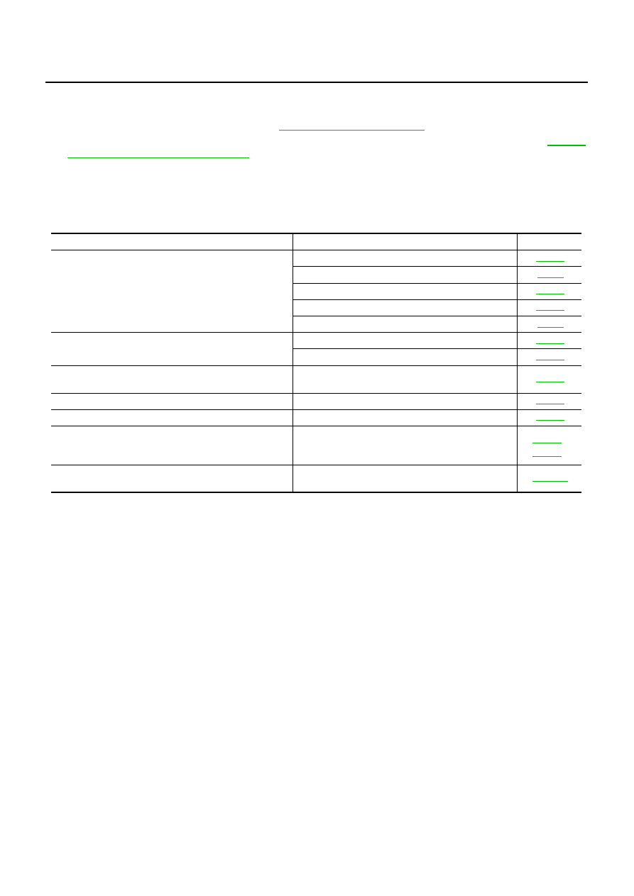
3.
CHECK GROUND CIRCUIT
1.
Turn ignition switch OFF.
2.
Disconnect BCM connector.
3.
Check continuity between BCM connector and ground.
OK or NG
OK
>> Power supply and ground circuit are OK.
NG
>> Check BCM ground circuit for open or short.
Terminals
Condition of
ignition switch
Voltage (V)
(Approx.)
(+)
(–)
BCM connector
Terminal
M1
38
Ground
ON
Battery voltage
M2
42
OFF
55
PIIB5934E
BCM connector
Terminal
Ground
Continuity
M2
52
Yes
PIIB5935E
GW-84
REAR WINDOW DEFOGGER
Check Rear Window Defogger Switch Circuit
NIS0022S
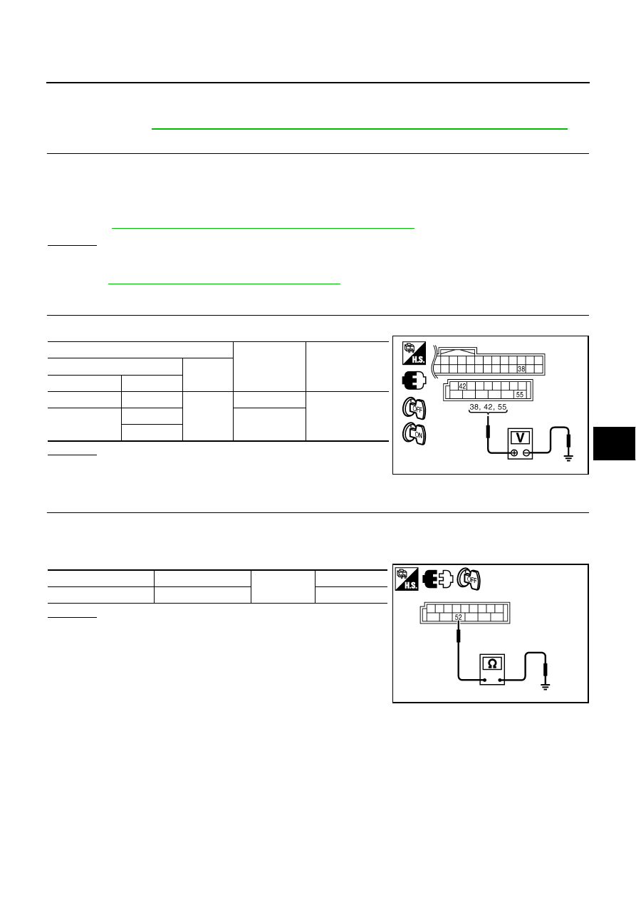
1.
CHECK REAR WINDOW DEFOGGER SWITCH OPERATION
With CONSULT-II
Check (“REAR DEF SW”, “IGN ON SW”) in DATA MONITOR mode with CONSULT-II.
OK or NG
OK
>> Rear window defogger switch is OK.
NG
>> GO TO 2.
2.
CHECK AV LINE
Check AV line. Refer to
(without navigation system).
OK or NG
OK
>> Check the condition of harness and connector.
NG
>> The diagnosis is continued.
Check Rear Window Defogger Power Supply Circuit
NIS0022T
1.
CHECK FUSE
●
Check 10A fuse [No.12, located in the fuse block (J/B)]
●
Check 20A fuse (No.75, located in the IPDM E/R)
●
Check 20A fuse (No.80, located in the IPDM E/R)
NOTE:
Refer to
GW-71, "Component Parts and Harness Connector Location"
OK or NG
OK
>> GO TO 2.
NG
>> If fuse is blown out, be sure to eliminate cause of malfunction before installing new fuse, refer to
PG-3, "POWER SUPPLY ROUTING CIRCUIT"
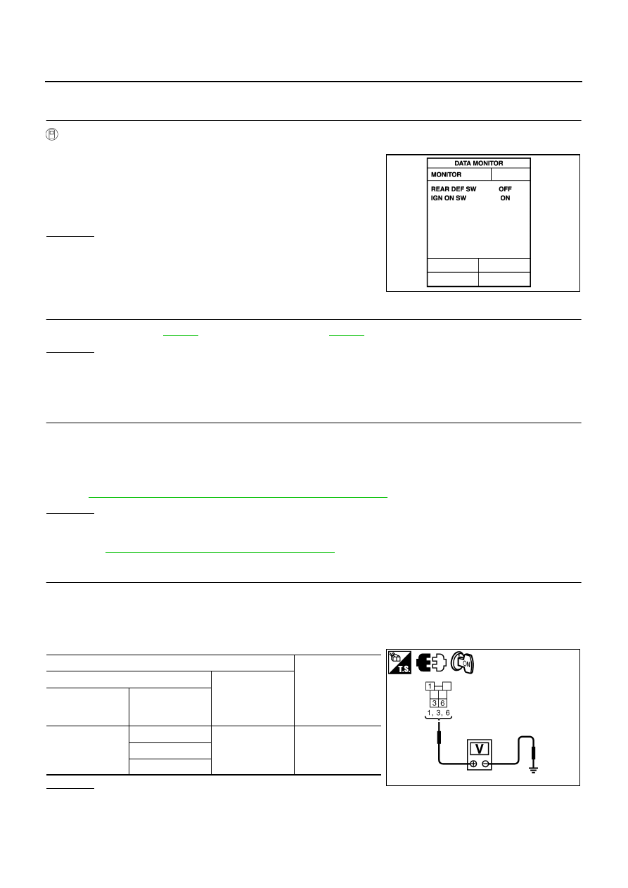
2.
CHECK POWER SUPPLY CIRCUIT
1.
Turn ignition switch OFF.
2.
Remove rear window defogger relay.
3.
Turn ignition switch ON.
4.
Check voltage between rear window defogger relay connector and ground.
OK or NG
OK
>> GO TO 3.
NG
>> Repair or replace harness between fuse block (J/B) and rear window defogger relay.
When rear window defogger switch is turned to ON
REAR DEF SW
: ON
When ignition switch is turned to ON
IGN ON SW
: ON
PIIA2373E
Terminals
Voltage (V)
(Approx.)
(+)
(–)
Rear window
defogger relay
connector
Terminal
E36
1
Ground
Battery voltage
3
6
PIIB5994E
Нет комментариевНе стесняйтесь поделиться с нами вашим ценным мнением.
Текст