Infiniti M35/M45 Y50. Manual — part 818
INSIDE MIRROR
GW-69
C
D
E
F
G
H
J
K
L
M
A
B
GW
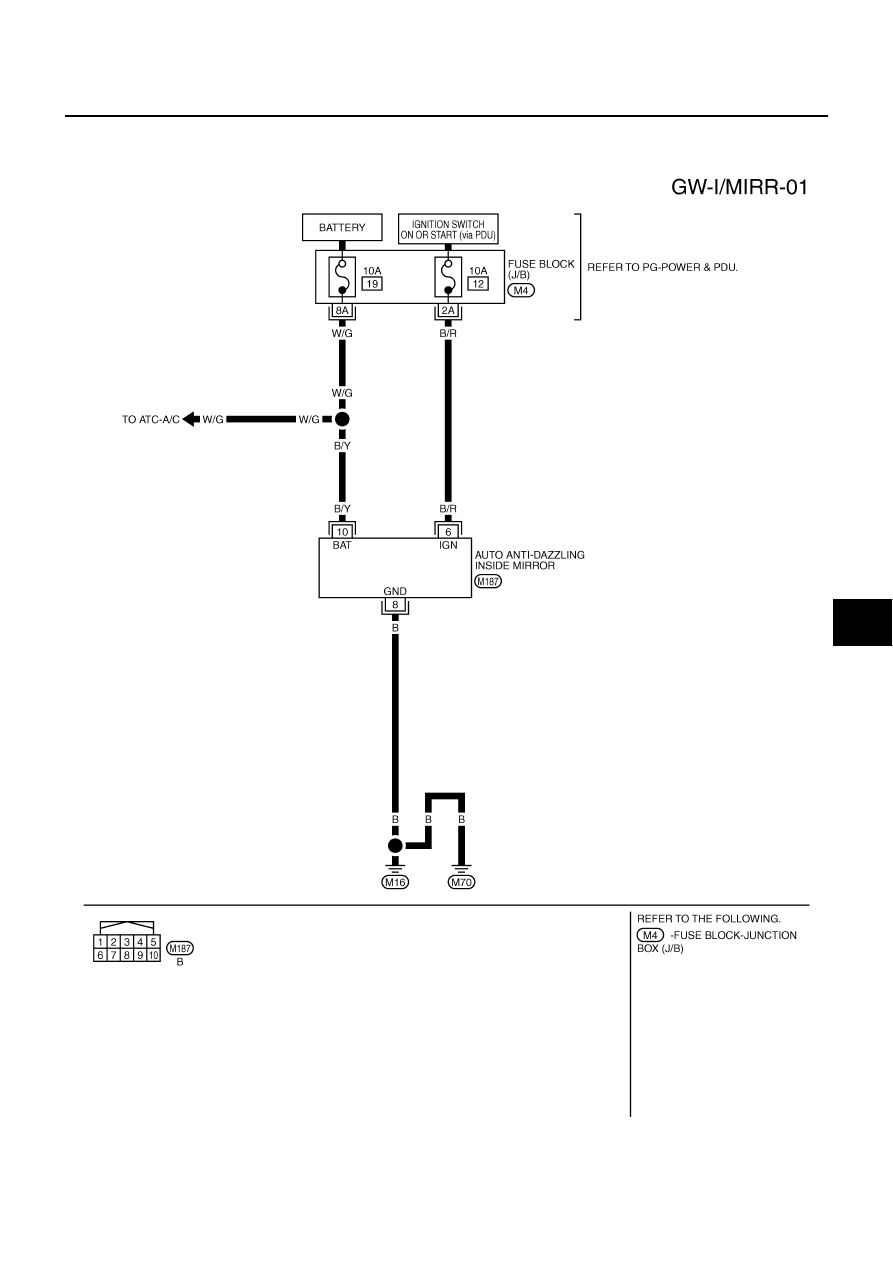
INSIDE MIRROR
PFP:96321
Wiring Diagram –I/MIRR–
NIS0022E
TIWT2038E
GW-70
INSIDE MIRROR
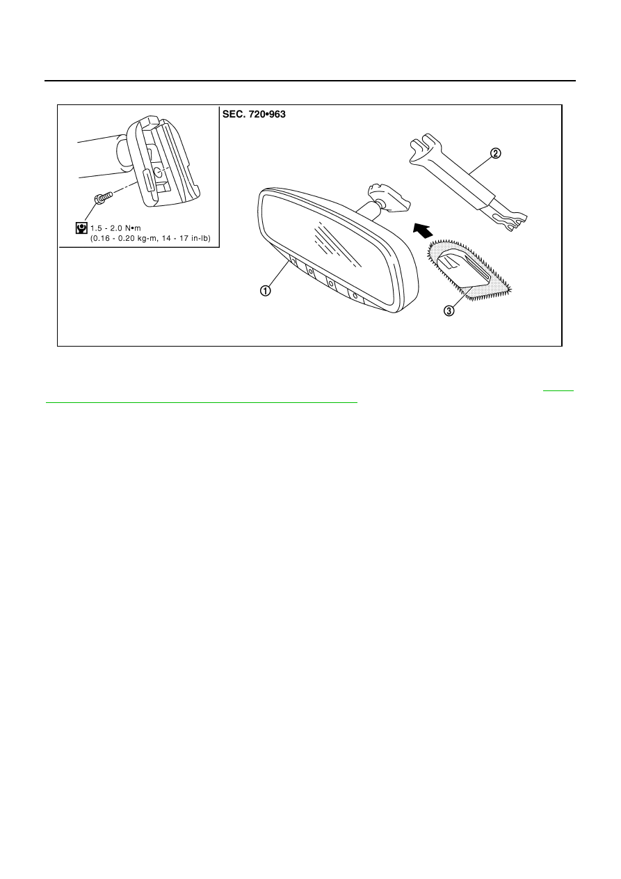
Removal and Installation
NIS0022F
CAUTION:
Apply Genuine Mirror Adhesive or equivalent to bonding surface of mounting bracket. Refer to
"RECOMMENDED CHEMICAL PRODUCTS AND SEALANTS"
REMOVAL
1.
Remove inside mirror finisher (if equipped).
2.
Remove screw of mirror base.
3.
Slide the mirror upward to remove.
4.
Disconnect the connector (if equipped).
INSTALLATION
Install in the reverse order of removal.
1.
Inside mirror
2.
Inside mirror finisher (if equipped)
3.
Mirror base
PIIB5780E

REAR WINDOW DEFOGGER
GW-71
C
D
E
F
G
H
J
K
L
M
A
B
GW
REAR WINDOW DEFOGGER
PFP:25350
Component Parts and Harness Connector Location
NIS0022G
System Description
NIS0022H
The rear window defogger system is controlled by BCM and IPDM E/R.
The rear window defogger operates only for approximately 15 minutes.
Power is at all times supplied
●
through 20A fuse [No. 75, located in the IPDM E/R]
●
to rear window defogger relay terminals 6,
●
through 20A fuse [No. 80, located in the IPDM E/R]
●
to rear window defogger relay terminals 3,
●
through 15A fuse [No. 37, located in the fuse and fusible link box
●
to multi-function switch terminal 1,
PIIB6098E
1.
Fuse block (J/B)
2.
Fuse and fusible link box
3.
Fuse block (in IPDM E/R)
4.
IPDM E/R E4, E8, E9
5.
BCM M1, M2
6.
Rear window defogger switch (in
multi function switch) M69
7.
Rear window defogger relay E36
8.
a : Rear window defogger B604,B701
b : Condenser B49
GW-72
REAR WINDOW DEFOGGER
●
through 50A fusible link (letter F , located in the fuse and fusible link box)
●
to BCM terminal 55,
●
through 10A fuse [No. 21, located in the fuse block (J/B)]
●
to BCM terminal 42.
With the ignition switch turned to ON or START position,
Power is supplied
●
through 15A fuse [No. 1, located in the fuse block (J/B)]
●
to BCM terminal 38.
●
through 10A fuse [No. 12, located in the fuse block (J/B)]
●
to rear window defogger relay terminal 1.
With the ignition switch turned to ACC or ON position,
●
through 10A fuse [No. 6, located in the fuse block (J/B)]
●
to multi-function switch terminal 2.
Ground is supplied
●
to BCM terminal 52
●
through body grounds M16 and M70,
●
to multi-function switch terminal 14
●
through body grounds M16 and M70,
●
to IPDM E/R terminals 38 and 51
●
through body grounds E22 and E43.
When rear window defogger switch in multi-function switch is turned to ON.
Then multi-function switch recognizes that rear window defogger switch is turned to ON.
Then it sends rear window defogger switch signals to AV control unit (without navigation system) or NAVI con-
trol unit (with navigation system) via AV line.
When AV control unit (without navigation system) or NAVI control unit (with navigation system) receives rear
window defogger switch signals, and display on the screen.
Then AV control unit (without navigation system) or NAVI control unit (with navigation system) recognizes that
rear window defogger switch is turned to ON.
Then it sends rear window defogger switch signal to BCM via DATA LINE (CAN H, CAN L).
Then BCM recognizes that rear window defogger switch signal.
Then it sends rear window defogger request signal to IPDM E/R via DATA LINE (CAN H, CAN L).
When IPDM E/R receives rear window defogger switch signals,
Ground is supplied
●
to rear window defogger relay terminal 2
●
through IPDM E/R terminal 57
●
through IPDM E/R terminal 51
●
through body grounds E22 and E43.
And then rear window defogger relay is energized.
When rear window defogger relay is turned ON, signals are transmitted.
●
through rear window defogger relay terminals 5 and 7
●
through condenser terminal 1
●
to rear window defogger terminal 1
Rear window defogger terminal 2 is grounded through grounds B702.
With power and ground supplied, rear window defogger filaments heat and defog the rear window.
When rear window defogger relay is turned to ON,
Power is supplied
●
through rear window defogger relay terminals 5 and 7
●
through fuse block (J/B) terminal 2C
●
through 10A fuse [No. 8, located in the fuse block (J/B)] and
●
through fuse block (J/B) terminal 5B
●
to door mirror (LH and RH) terminal 4.
Door mirror (LH and RH) terminal 8 is grounded through body grounds M16 and M70.
Нет комментариевНе стесняйтесь поделиться с нами вашим ценным мнением.
Текст