Infiniti M35/M45 Y50. Manual — part 923
COMBINATION SWITCH
LT-237
C
D
E
F
G
H
I
J
L
M
A
B
LT
36
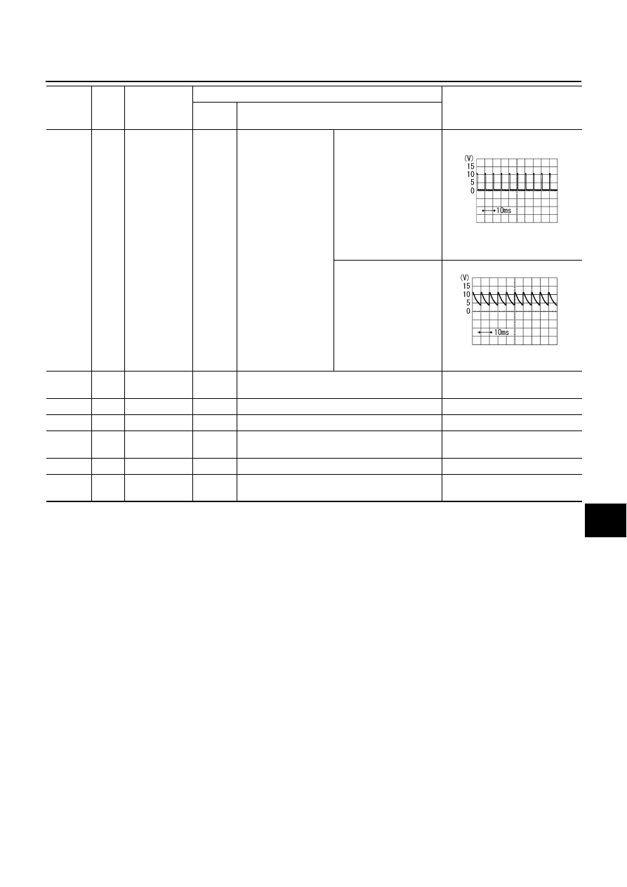
V
Combination
switch output 1
ON
Lighting, turn, wiper
switch
(Wiper dial position 4)
Any of several con-
ditions below
●
Turn signal switch
right
●
Turn signal switch left
●
Front wiper switch
MIST
●
Front wiper switch LO
●
Front washer switch
Approx. 1.2 V
OFF
(Wiper dial position 4)
Approx. 7.0 - 7.5 V
38
W
Ignition switch
(ON)
ON
—
Battery voltage
39
L
CAN
−
H
—
—
—
40
P
CAN
−
L
—
—
—
42
P
Battery power
supply
OFF
—
Battery voltage
52
B
Ground
ON
—
Approx. 0 V
55
W
Battery power
supply
OFF
—
Battery voltage
Terminal
No.
Wire
color
Signal name
Measuring condition
Reference value
Ignition
switch
Operation or condition
PKIB4958J
PKIB4960J

LT-238
COMBINATION SWITCH
CONSULT-II Functions (BCM)
NKS003S8
CONSULT-II can display each diagnostic item using the diagnostic test mode shown following.
CONSULT-II BASIC OPERATION
Refer to
GI-38, "CONSULT-II Start Procedure"
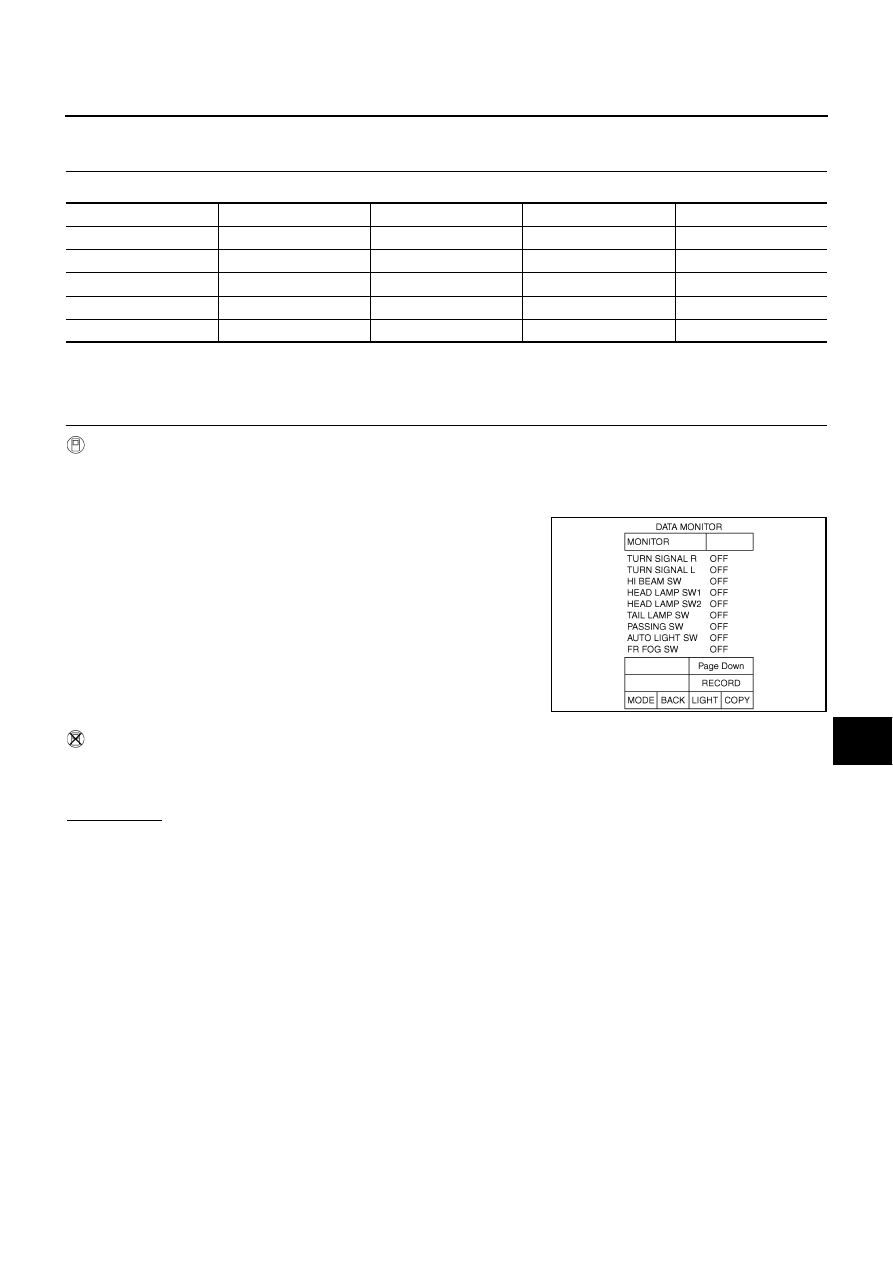
DATA MONITOR
Operation Procedure
1.
Touch “COMB SW” on “SELECT TEST ITEM” screen.
2.
Touch “DATA MONITOR” on “SELECT DIAG MODE” screen.
3.
Touch either “ALL SIGNALS” or “SELECTION FROM MENU” on “SELECT MONITOR ITEM” screen.
4.
When “SELECTION FROM MENU” is selected, touch items to be monitored. When “ALL SIGNALS” is
selected, all the signals will be monitored.
5.
Touch “START”.
6.
Touch “RECORD” while monitoring, then the status of the monitored item can be recorded. To stop
recording, touch “STOP”.
Display Item List
BCM diagnosis part
Diagnosis mode
Description
COMB SW
DATA MONITOR
Displays BCM input data in real time.
ALL SIGNALS
Monitors all the signals.
SELECTION FROM MENU
Selects items and monitor them.
Monitor item name
Contents
TURN SIGNAL R
“ON/OFF”
Displays “turn right (ON)/other (OFF)” status, determined from lighting switch signal.
TURN SIGNAL L
“ON/OFF”
Displays “turn left (ON)/other (OFF)” status, determined from lighting switch signal.
HI BEAM SW
“ON/OFF”
Displays status (high beam switch: ON/others: OFF) of high beam switch judged from lighting
switch signal.
HEAD LAMP SW 1
“ON/OFF”
Displays status (headlamp switch 1: ON/others: OFF) of headlamp switch 1 judged from lighting
switch signal.
HEAD LAMP SW 2
“ON/OFF”
Displays status (headlamp switch 2: ON/others: OFF) of headlamp switch 2 judged from lighting
switch signal.
TAIL LAMP SW
“ON/OFF”
Displays status (lighting switch 1ST or 2ND position: ON/others: OFF) of lighting switch judged from
lighting switch signal.
PASSING SW
“ON/OFF”
Displays status (flash-to-pass switch: ON/others: OFF) of flash-to-pass switch judged from lighting
switch signal.
AUTO LIGHT SW
“ON/OFF”
Displays “auto light switch (ON)/other (OFF)” status, determined from lighting switch signal.
FR FOG SW
“ON/OFF”
Displays “front fog lamp switch (ON)/other (OFF)” status, determined from lighting switch signal.
FR WIPER HI
“ON/OFF”
Displays “front wiper HI (ON)/other (OFF)” status, determined from wiper switch signal.
FR WIPER LOW
“ON/OFF”
Displays “front wiper LOW (ON)/other (OFF)” status, determined from wiper switch signal.
FR WIPER INT
“ON/OFF”
Displays “front wiper INT (ON)/other (OFF)” status, determined from wiper switch signal.
FR WASHER SW
“ON/OFF”
Displays “front washer switch (ON)/other (OFF)” status, determined from wiper switch signal.
INT VOLUME
“1 - 7”
Displays intermittent operation knob setting (1 - 7), determined from wiper switch signal.
COMBINATION SWITCH
LT-239
C
D
E
F
G
H
I
J
L
M
A
B
LT
Combination Switch Inspection
NKS003S9
1.
SYSTEM CHECK
Referring to table below, check the system to which malfunctioning switch belongs.
>> Check the system to which malfunctioning switch belongs, and then GO TO 2.
2.
SYSTEM CHECK
With CONSULT-II
CAUTION:
If CONSULT-II is used with no connection of CONSULT-II CONVERTER, malfunctions might be
detected in self-diagnosis depending on control unit which carry out CAN communication.
1.
Connect CONSULT-II, and select “COMB SW” on “SELECT
TEST ITEM” screen.
2.
Select “DATA MONITOR”.
3.
Select “START”, and confirm that other switches in malfunction-
ing system operate normally.
Example: When the HI BEAM switch is malfunctioning, confirm
that “TURN RH”, “HEAD LAMP 1” and “TAIL LAMP SW” in Sys-
tem 5, to which the HI BEAM switch belongs, turn ON-OFF nor-
mally.
Without CONSULT-II
Operating combination switch, and confirm that other switches in malfunctioning system operate normally.
Example: When the HI BEAM switch is malfunctioning, confirm that “TURN RH”, “HEAD LAMP 1” and “TAIL
LAMP SW” in System 5, to which HI BEAM switch belongs, turn ON-OFF normally.
Check results
Other switches in malfunctioning system operate normally.>>Replace lighting switch or wiper switch.
Other switches in malfunctioning system do not operate normally.>>GO TO 3.
System 1
System 2
System 3
System 4
System 5
—
FR WASHER
FR WIPER LO
TURN LH
TURN RH
FR WIPER HI
—
FR WIPER INT
PASSING
HEAD LAMP1
INT VOLUME 1
—
—
HEAD LAMP2
HI BEAM
—
INT VOLUME 3
AUTO LIGHT
—
LIGHT SW 1ST
INT VOLUME 2
—
—
FR FOG
—
SKIB4816E
LT-240
COMBINATION SWITCH
3.
CHECK HARNESS
1.
Turn ignition switch OFF.
2.
Disconnect BCM and combination switch connectors.
3.
Check for continuity between BCM harness connector (A) of the suspect system and the corresponding
combination switch connector (B).
4.
Check for continuity between each of BCM harness connector in suspect malfunctioning system and
ground.
OK or NG
OK
>> GO TO 4.
NG
>> Check harness between BCM and combination switch for open or short circuit.
Sus-
pect
system
A
B
Continuity
Connector
Terminal
Connector
Terminal
1
M1
Input 1
6
M29
6
Yes
Output 1
36
1
2
Input 2
5
7
Output 2
35
2
3
Input 3
4
10
Output 3
34
3
4
Input 4
3
9
Output 4
33
4
5
Input 5
2
8
Output 5
32
5
Suspect
system
BCM
connector
Terminal
Ground
Continuity
1
M1
Input 1
6
No
Output 1
36
2
Input 2
5
Output 2
35
3
Input 3
4
Output 3
34
4
Input 4
3
Output 4
33
5
Input 5
2
Output 5
32
SKIB4819E
PKIA7506E
Нет комментариевНе стесняйтесь поделиться с нами вашим ценным мнением.
Текст