Infiniti M35/M45 Y50. Manual — part 141
TROUBLE DIAGNOSIS
ATC-115
C
D
E
F
G
H
I
K
L
M
A
B
ATC
In-vehicle Sensor Circuit
NJS000H1
COMPONENT DESCRIPTION
In-vehicle Sensor
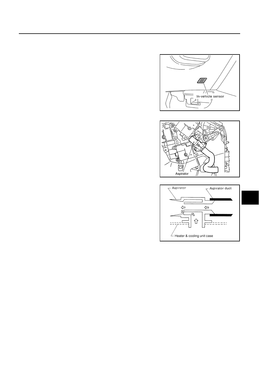
The in-vehicle sensor is located on instrument driver lower panel. It
converts variations in temperature of compartment air drawn from
the aspirator into a resistance value. It is then input into the unified
meter and A/C amp.
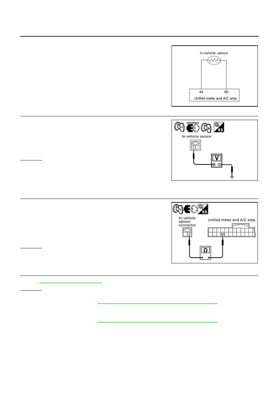
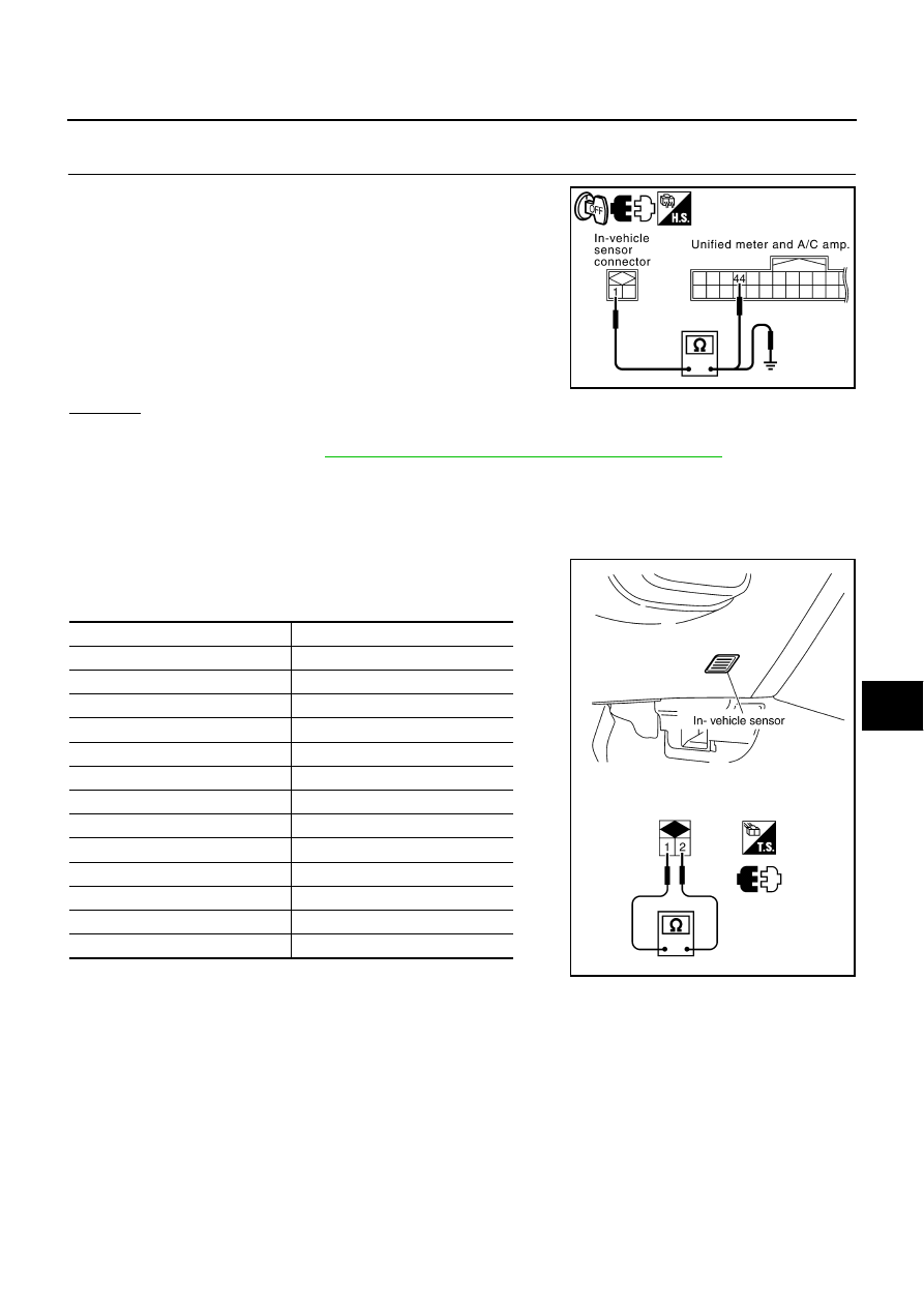
Aspirator
The aspirator is located on driver’s side of heater & cooling unit
assembly. It produces vacuum pressure due to air discharged from
the heater & cooling unit assembly, continuously taking compartment
air in the aspirator.
RJIA4092E
RJIA4093E
RJIA1804E
ATC-116
TROUBLE DIAGNOSIS
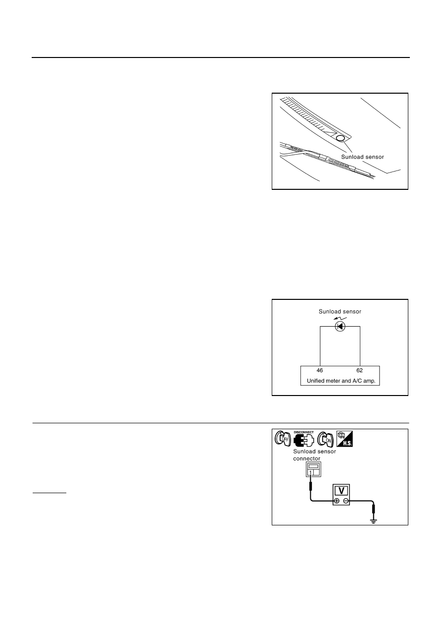
DIAGNOSIS PROCEDURE FOR IN-VEHICLE SENSOR
SYMPTOM: In-vehicle sensor circuit is open or shorted. (22 or
−
22 is
indicated on unified meter and A/C amp. as a result of performing
self-diagnosis STEP-2.)
1.
CHECK VOLTAGE BETWEEN IN-VEHICLE SENSOR AND GROUND
1.
Disconnect in-vehicle sensor connector.
2.
Turn ignition switch ON.
3.
Check voltage between in-vehicle sensor harness connector
M54 terminal 1 and ground.
OK or NG
OK
>> GO TO 2.
NG
>> GO TO 4.
2.
CHECK CIRCUIT CONTINUITY BETWEEN IN-VEHICLE SENSOR AND UNIFIED METER AND A/C
AMP.
1.
Turn ignition switch OFF.
2.
Disconnect unified meter and A/C amp. connector.
3.
Check continuity between in-vehicle sensor harness connector
M54 terminal 2 and unified meter and A/C amp. harness con-
nector M65 terminal 60.
OK or NG
OK
>> GO TO 3.
NG
>> Repair harness or connector.
3.
CHECK IN-VEHICLE SENSOR
Refer to
.
OK or NG
OK
>> 1. Replace unified meter and A/C amp.
2. Go to self-diagnosis
ATC-57, "FUNCTION CONFIRMATION PROCEDURE"
and perform self-
diagnosis STEP-2. Confirm that code No. 20 is displayed.
NG
>> 1. Replace in-vehicle sensor.
2. Go to self-diagnosis
ATC-57, "FUNCTION CONFIRMATION PROCEDURE"
and perform self-
diagnosis STEP-2. Confirm that code No. 20 is displayed.
RJIA4094E
1 – Ground
: Approx. 5 V
RJIA2022E
2 – 60
: Continuity should exist.
RJIA4095E
TROUBLE DIAGNOSIS
ATC-117
C
D
E
F
G
H
I
K
L
M
A
B
ATC
4.
CHECK CIRCUIT CONTINUITY BETWEEN IN-VEHICLE SENSOR AND UNIFIED METER AND A/C
AMP.
1.
Turn ignition switch OFF.
2.
Disconnect unified meter and A/C amp. connector.
3.
Check continuity between in-vehicle sensor harness connector
M54 terminal 1 and unified meter and A/C amp. harness con-
nector M65 terminal 44.
4.
Check continuity between in-vehicle sensor harness connector
M54 terminal 1 and ground.
OK or NG
OK
>> 1. Replace unified meter and A/C amp.
2. Go to self-diagnosis
ATC-57, "FUNCTION CONFIRMATION PROCEDURE"
and perform self-
diagnosis STEP-2. Confirm that code No. 20 is displayed.
NG
>> Repair harness or connector.
COMPONENT INSPECTION
In-vehicle Sensor
After disconnecting in-vehicle sensor connector M54, measure resis-
tance between terminals 1 and 2 at sensor side. Refer to the table
below.
If NG, replace in-vehicle sensor.
1 – 44
: Continuity should exist.
1 – Ground
: Continuity should not exist.
RJIA4096E
Temperature
°
C (
°
F)
Resistance k
Ω
−
15 (5)
12.73
−
10 (14)
9.92
−
5 (23)
7.80
0 (32)
6.19
5 (41)
4.95
10 (50)
3.99
15 (59)
3.24
20 (68)
2.65
25 (77)
2.19
30 (86)
1.81
35 (95)
1.51
40 (104)
1.27
45 (113)
1.07
RJIA4097E
ATC-118
TROUBLE DIAGNOSIS
Sunload Sensor Circuit
NJS000H2
COMPONENT DESCRIPTION
Sunload Sensor
The sunload sensor is located on the driver’s side front defroster
grille. It detects sunload entering through windshield by means of a
photo diode. The sensor converts the sunload into a current value
which is then input into the unified meter and A/C amp.
SUNLOAD INPUT PROCESS
The unified meter and A/C amp. also includes a processing circuit which averages the variations in detected
sunload over a period of time. This prevents drastic swings in the ATC system operation due to small or quick
variations in detected sunload.
For example, consider driving along a road bordered by an occasional group of large trees. The sunload
detected by the sunload sensor will vary whenever the trees obstruct the sunlight. The processing circuit aver-
ages the detected sunload over a period of time, so that the (insignificant) effect of the trees momentarily
obstructing the sunlight does not cause any change in the ATC system operation. On the other hand, shortly
after entering a long tunnel, the system will recognize the change in sunload, and the system will react accord-
ingly.
DIAGNOSIS PROCEDURE FOR SUNLOAD SENSOR
SYMPTOM: Sunload sensor circuit is open or shorted. (25 or
−
25 is
indicated on unified meter and A/C amp. as a result of performing
self-diagnosis STEP-2.)
1.
CHECK VOLTAGE BETWEEN SUNLOAD SENSOR AND GROUND
1.
Disconnect sunload sensor connector.
2.
Turn ignition switch ON.
3.
Check voltage between sunload sensor harness connector M87
terminal 1 and ground.
OK or NG
OK
>> GO TO 2.
NG
>> GO TO 4.
RJIA4098E
RJIA4099E
1 – Ground
: Approx. 5 V
RJIA2027E
Нет комментариевНе стесняйтесь поделиться с нами вашим ценным мнением.
Текст